
Overview
Specifications
| ParameterSpecification | |
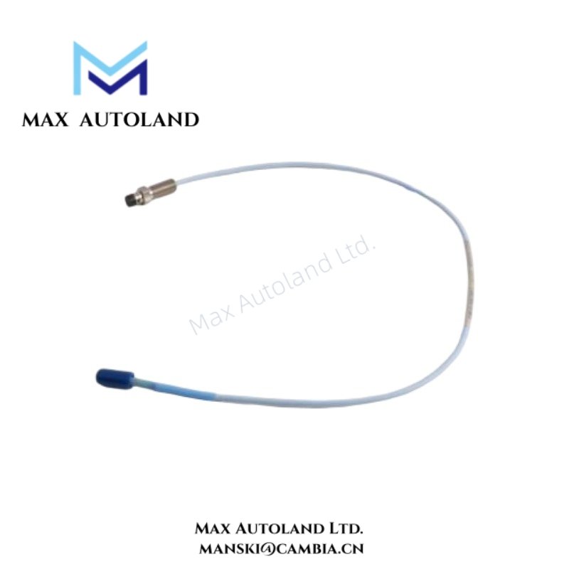
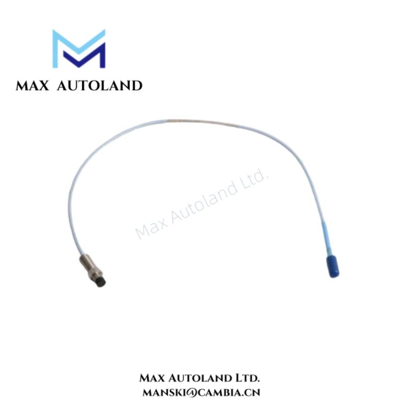
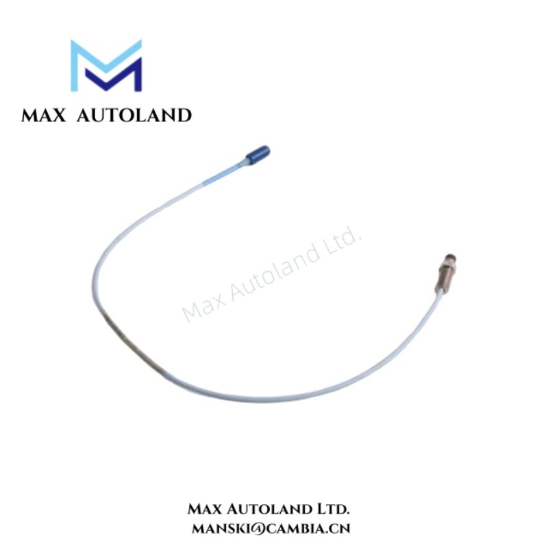
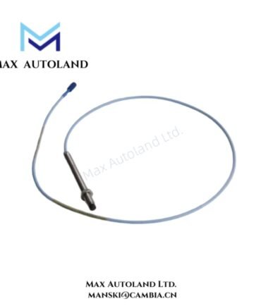
| Model | 330195-02-12-05-00 |
| Brand | Bently Nevada |
| Origin | USA |
| Product Type | Proximity Transducer (Eddy Current Probe) |
| Series | 3300 XL 8 mm |
| Measurement Principle | Eddy-current displacement sensing |
| Application | Shaft vibration and position monitoring |
| Signal Interface | Proximitor-compatible analog output |
| Weight | Not specified in provided data |
| Dimensions | Not specified in provided data |
| Operating Temp | Not specified in provided data |
| Power Consumption | Passive sensor; excitation from Proximitor driver |
Eddy-Current Probe Scaling and Signal Integrity Control
Within Bently Nevada 3300 XL architectures, probe calibration is directly linked to eddy-current field linearity and target material response. The 8 mm probe geometry establishes a defined sensitivity range for radial shaft displacement measurement, where output voltage varies proportionally with gap distance.
During commissioning, engineers validate probe scaling against expected gap response curves. Typical setup procedures include verification of -10 VDC bias reference conditions at defined air gap positions. This confirms correct probe orientation, driver excitation stability, and conductive target coupling.
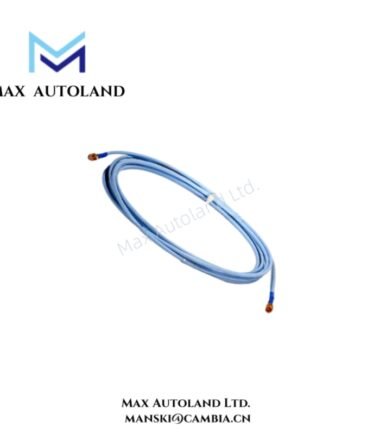
Signal integrity depends on controlled impedance behavior across probe, extension cable, and Proximitor input stage. Any discontinuity in shielding or connector engagement can introduce cross-talk, amplitude drift, or phase distortion in rotor dynamic measurements.
Frequently Asked Questions
Q: Does the 330195-02-12-05-00 require external excitation power?
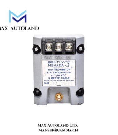
A: The probe does not use independent excitation. It receives energy from the associated Proximitor driver, which supplies the eddy-current excitation field.
Q: Can the probe be interchanged with other 3300 XL probe lengths without recalibration?
A: Probe length variation changes system scaling characteristics. Recalibration of the probe-to-Proximitor loop is required after replacement.
Q: What limits signal stability in high-noise environments?
A: Shield termination quality, cable routing separation, and connector integrity primarily determine noise immunity in eddy-current measurement loops.
Field Installation Guidelines
Install the probe with controlled mechanical clearance to maintain the specified measurement gap range. Ensure the probe face remains aligned perpendicular to the monitored shaft surface.
Route probe cables away from high-current conductors, variable frequency drives, and switching power lines. Maintain continuous shield termination from probe to Proximitor input without interruption points.
After installation, verify connector seating torque and inspect for mechanical stress at bend points. Improper routing can introduce measurement drift, noise coupling, or unstable gap voltage behavior.







Reviews
There are no reviews yet.