

Overview
Suffix Breakdown & Model Matrix
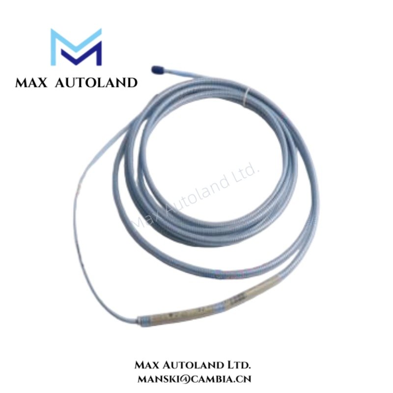
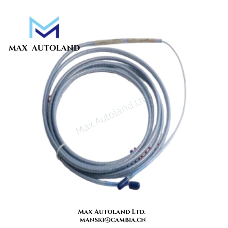
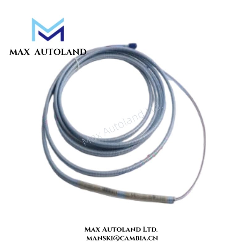
The supplied documentation identifies 330190-045-00-00 as a fixed configured extension cable variant within the Bently Nevada 3300 XL 8 mm Proximity Transducer family. The provided material does not define a formal suffix decoding matrix; therefore, no further suffix expansion appears here.
Specifications
| ParameterSpecification | |
| Model | 330190-045-00-00 |
| Brand | Bently Nevada |
| Origin | USA |
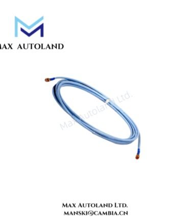
| Product Type | Extension Cable |
| Series | 3300 XL 8 mm Proximity Transducer |
| Application | Probe-to-Proximitor signal extension |
| Signal Type | Eddy-current transducer interface signal path |
| Connector Interface | Factory-configured cable termination assembly |
| Weight | Not specified in supplied material |
| Dimensions | Not specified in supplied material |
| Operating Temp | Not specified in supplied material |
| Power Consumption | Passive component; no independent power input identified |
Gap Voltage Validation and Eddy-Current Signal Scaling
Within Bently Nevada TSI and vibration monitoring systems, extension cable characteristics directly affect eddy-current probe scaling, gap reference stability, and overall channel behavior. Consequently, engineers verify cable continuity, shield integrity, and connector engagement during commissioning.
For 3300 XL transducer loops, setup practice often includes gap voltage validation against expected operating targets, frequently near -10 VDC. This procedure confirms probe positioning, conductive target response, and signal path integrity. In addition, consistent cable impedance and controlled shielding reduce common-mode noise pickup, suppress cross-channel interference, and support repeatable rotor dynamic measurements.
Frequently Asked Questions
Q: Does the 330190-045-00-00 support hot replacement during energized rack operation?
A: The supplied material does not define a hot-swap classification. Therefore, standard maintenance practice isolates monitoring power, verifies signal de-energization, and then performs cable removal or installation.
Q: Does the extension cable perform active signal conditioning or amplification?
A: No active electronics appear in the available documentation. The assembly functions as a passive signal extension component within the transducer measurement loop.
Q: Which wiring practice supports low-noise transducer operation?
A: Route the cable separately from motor feeders, switching conductors, and VFD output wiring. In addition, maintain shield continuity and apply grounding methods that match system documentation and site grounding rules.
Field Installation Guidelines
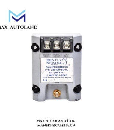
Verify cable part number compatibility before installation and confirm alignment with the associated 3300 XL probe and Proximitor assembly.
Route the extension cable with controlled bend management and maintain separation from high-current or high-frequency conductors. Furthermore, preserve shield termination integrity across the complete measurement loop.
After connection, inspect connector seating and mechanical retention points. Poor engagement can increase contact resistance, introduce intermittent signal behavior, and alter measured gap voltage stability.




Reviews
There are no reviews yet.