

Overview
Specifications
| ParameterSpecification | |
| Model | 330130-075-00-00 |
| Brand | Bently Nevada |
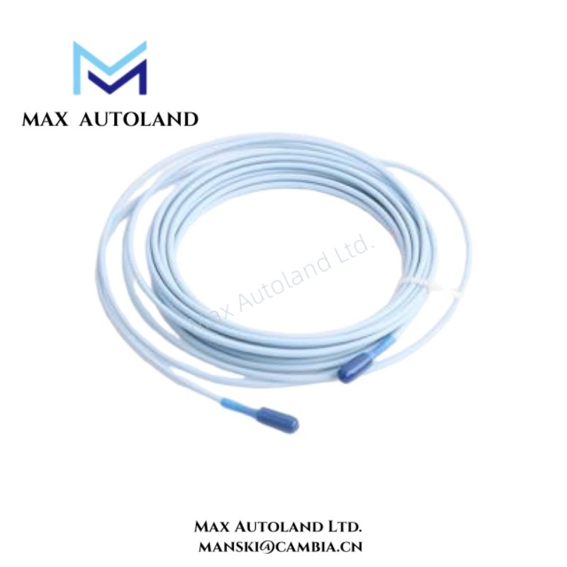
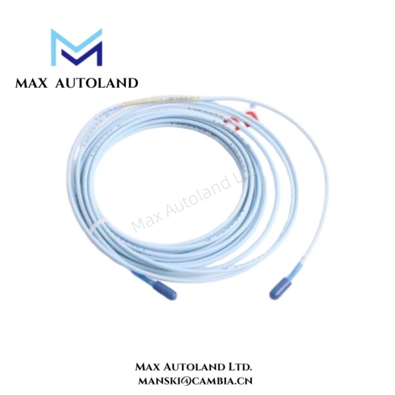
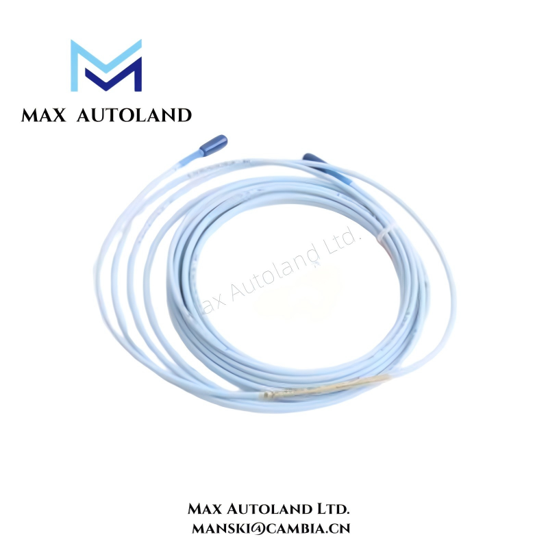
| Product Type | Extension Cables |
| Series | 3300 XL 8 mm Proximity Transducer |
| Functional Role | Probe-to-sensor signal extension |
| Associated System | Bently Nevada 3300 XL 8 mm System |
| Origin | United States |
| Weight | Not specified in supplied material |
| Dimensions | Not specified in supplied material |
| Operating Temp | Not specified in supplied material |
| Power Consumption | Passive component; no independent power draw |
| Signal Type | Eddy-current transducer signal path |
| Cable Construction | Factory-configured extension cable assembly |
Eddy-Current Probe Scaling and Gap Voltage Validation
Within Bently Nevada transducer architectures, the extension cable forms part of a matched measurement loop that includes the probe, extension cable, and Proximitor sensor. Consequently, cable substitution requires compatibility with the designated 3300 XL calibration set.
During commissioning, technicians commonly verify probe gap voltage against expected operating targets, frequently near -10 VDC, to confirm probe position, conductive target response, and signal loop integrity. In addition, connector engagement quality, shield continuity, and cable routing practice directly influence noise immunity and scaling stability.
Frequently Asked Questions
Q: Can the 330130-075-00-00 extension cable support hot replacement while the monitoring channel remains energized?
A: The supplied material does not define a hot-swap rating. Standard maintenance practice therefore isolates channel power and confirms a safe signal state before cable removal or installation.
Q: Does this extension cable provide active amplification or signal conditioning?
A: No. The 330130-075-00-00 functions as a passive extension element within the 3300 XL transducer system. The assembly does not perform independent amplification, filtering, or signal conversion.
Q: What installation practice supports low-noise signal performance?
A: Route the cable separately from motor feeders, switching power conductors, and variable frequency drive outputs. In addition, maintain connector cleanliness, preserve shield continuity, and follow the applicable grounding method defined for the monitoring system.
Field Installation Guidelines
Verify model compatibility between the probe, extension cable, and Proximitor sensor before installation. Mixed-component configurations can alter calibrated response characteristics.
Use controlled routing practices to reduce inductive and capacitive coupling into low-level transducer circuits. Furthermore, avoid tight parallel runs with high-current wiring and protect cable assemblies from mechanical strain, abrasion, and excessive bend loading.
After installation, inspect connector seating and cable retention points. Incomplete connector engagement can introduce unstable gap voltage behavior, elevated noise levels, or intermittent signal transmission.







Reviews
There are no reviews yet.