
Overview
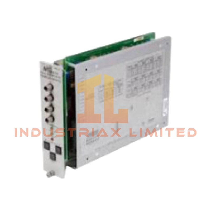
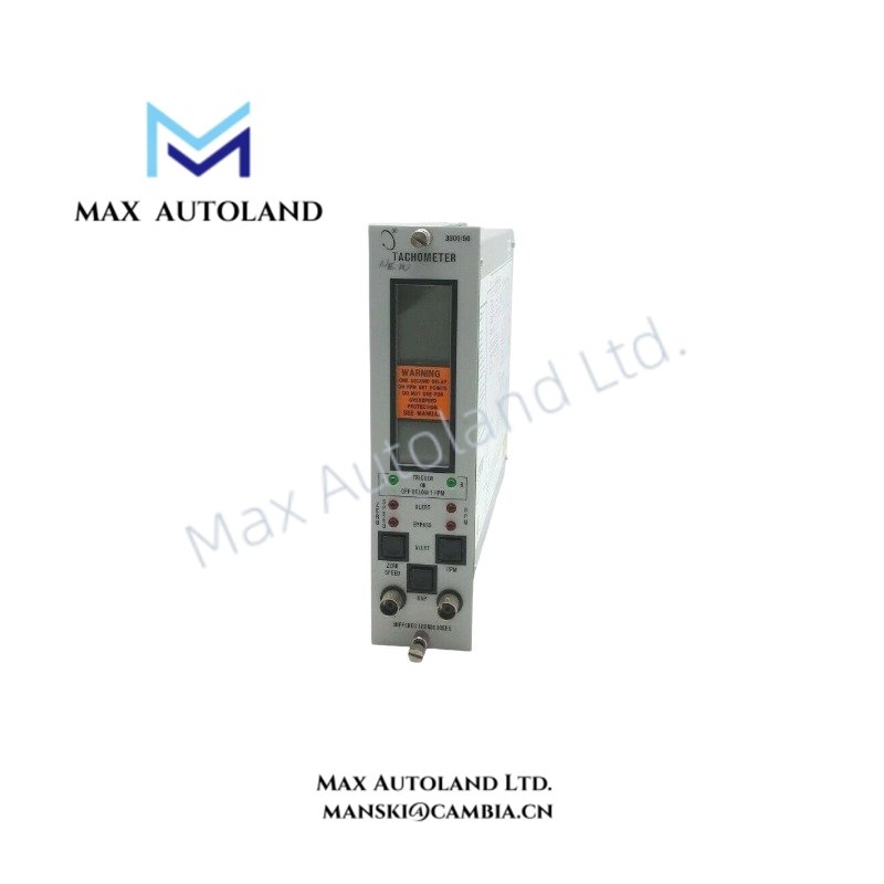
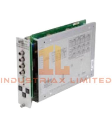
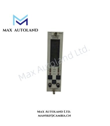
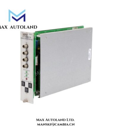
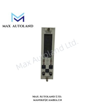
The Bently Nevada 3300/50 Tachometer Monitor, also cataloged as the 3300/50 Tachometer Monitor, operates as a dedicated hardware component for shaft speed measurement, acceleration monitoring, and zero speed detection within the Bently Nevada 3300 Monitoring System.
Hardware Specifications
| Parameter | Specification |
|---|---|
| Model | Bently Nevada 3300/50 Tachometer Monitor |
| Brand | Bently Nevada |
| Origin | USA |
| Product Type | Tachometer Monitor Module |
| Monitoring Function | Shaft speed, rotor acceleration/deceleration, and zero speed detection |
| System Platform | Bently Nevada 3300 Machinery Monitoring System |
| Input Channels | Single-channel monitor with dual transducer input capability |
| Supported Transducers | 3300 Series Proximity Probes, 7200 Series Proximity Probes, 3000 Series Proximity Probes, Magnetic Pickups |
| Input Impedance | 10 kOhm |
| Events per Revolution | Selectable from 1 to 255 |
| Speed Measurement Range | 1 to 99,999 rpm |
| Acceleration Range | -9,999 to +9,999 rpm/min |
| Zero Speed Threshold | Below 100 rpm |
| Speed Display Accuracy | +/- 1 rpm |
| Acceleration Display Accuracy | Within +/- 20 rpm/min |
| Recorder Output | 4-20 mA, 0 to -10 VDC, or +1 to +5 VDC |
| Current Output Load | 0 to 600 Ohm |
| Buffered Transducer Output | Two front-panel coaxial outputs with short-circuit protection |
| Output Impedance | 100 Ohm |
| Transducer Supply Voltage | -24 VDC or -18 VDC selectable through system power supply |
| Alarm Functions | Alert and Danger overspeed/underspeed alarms |
| Relay Interface | Two Alarm relay drives and one OK relay drive |
| Alarm Storage | Nonvolatile memory |
| Display Type | 5-digit LCD |
| Display Parameters | RPM, RPM/min, probe gap voltage, and Zero Speed status |
| Weight | Approx. 1.15 kg |
| Dimensions | 241 mm x 50 mm x 103 mm |
| Operating Temp | Not specified in supplied data |
| Power Consumption | 2.5 W nominal |
Bently Nevada Rotor Dynamics and Eddy-Current Signal Processing
The 3300/50 Tachometer Monitor processes input signals from eddy-current proximity probes and magnetic pickups to calculate shaft rotational parameters. Therefore, the module applies probe input conditioning to maintain stable speed measurement across different rotating equipment configurations.
The monitor supports Bently Nevada proximity probe systems by evaluating pulse events generated from rotating targets. Additionally, the selectable events-per-revolution configuration allows the module to adapt measurement calculations for different shaft geometries and target arrangements.
The module also supports gap voltage monitoring from compatible proximity probe inputs. Consequently, technicians can verify probe operating conditions by observing gap-related signals through the front-panel LCD display.
The 3300/50 uses dual transducer input voting logic to reduce false alarm conditions caused by a single sensor signal interruption. Furthermore, the design supports rotor dynamics monitoring functions by providing continuous speed and acceleration information for machinery analysis systems.
Frequently Asked Questions
Q: Can the Bently Nevada 3300/50 replace an overspeed protection system?
A: No. The 3300/50 provides tachometer monitoring and alarm annunciation functions. It does not perform dedicated emergency overspeed trip protection.
Q: How many transducer inputs can the module accept?
A: The module accepts up to two transducer inputs and applies internal voting logic between the two signals.
Q: What analog outputs does the 3300/50 provide for external systems?
A: The module provides programmable recorder outputs including 4-20 mA, 0 to -10 VDC, and +1 to +5 VDC signals for connection to recorders, DCS, or PLC systems.
Field Installation Guidelines
- Install the module in a compatible Bently Nevada 3300 rack position according to system configuration requirements.
- Connect proximity probe wiring using shielded cables to reduce electrical interference and signal noise.
- Ground cable shields according to plant instrumentation grounding practices while avoiding unwanted ground loops.
- Verify proximity probe polarity, signal routing, and connector condition before system startup.
- Confirm probe gap voltage values during commissioning to ensure correct eddy-current probe operating conditions.
- Route tachometer signal cables separately from high-current power conductors and switching circuits.
- Verify alarm setpoints and relay functions after installation before placing the monitoring channel into service.
- Use approved Bently Nevada configuration procedures when adjusting events-per-revolution parameters or measurement settings.




Reviews
There are no reviews yet.