
Overview
Hardware Specifications
| Parameter | Specification |
|---|---|
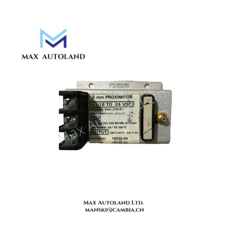
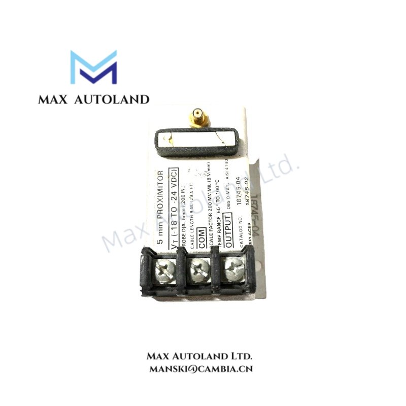
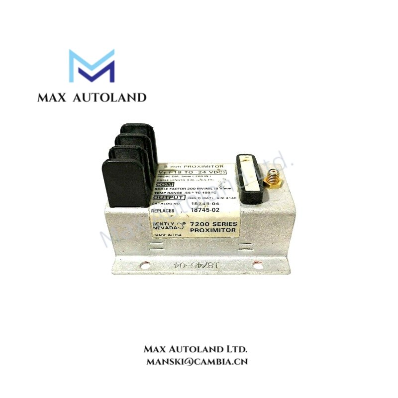
| Model | 18745-02 |
| Brand | Bently Nevada |
| Series | 7200 Series |
| Product Type | Proximitor Sensor |
| Measurement Type | Static displacement and dynamic vibration |
| Compatible Probe Diameters | 5 mm or 8 mm |
| Input Power | -18 VDC to -24 VDC |
| Power Consumption | Not specified |
| Frequency Response | 0 Hz to 10 kHz |
| Nominal Scale Factor | 200 mV/mil (7.87 mV/um) |
| Linear Range | Approximately 10 to 15 mil starting gap; linear measurement up to 80 mil depending on system calibration |
| Electrical Zero | -3.5 VDC at 20 mil gap |
| System Cable Length | 9 m total system length |
| Operating Temp | -51 degC to +100 degC |
| Dimensions | Not specified |
| Weight | Not specified |
| System Compatibility | Bently Nevada 3300 and 9000 Monitoring Systems |
| Compliance | API 670 compatible |
Eddy Current Probe Scaling and Gap Voltage Validation
The 18745-02 operates as the signal conditioning element of the 7200 Series eddy current measurement chain. The calibrated transfer function is based on a nominal sensitivity of 200 mV/mil, allowing proportional conversion of probe gap into output voltage. System calibration requires the specified probe, extension cable, and Proximitor Sensor combination to maintain scale factor accuracy.
Gap voltage validation is typically performed by verifying the electrical zero reference during commissioning. A nominal output of -3.5 VDC at a 20 mil target gap provides the reference point for subsequent rotor displacement measurements. Proper conductive target material, probe spacing, and complete 9 m system cable configuration are required to maintain calibration.
Frequently Asked Questions
Q: Can the 18745-02 operate with both 5 mm and 8 mm probes?
A: Yes. The sensor is designed for use with compatible 5 mm or 8 mm probes within the specified 7200 Series transducer system configuration.
Q: Is the sensor hot-swappable while connected to an operating monitoring rack?
A: The available product data does not specify hot-swap capability. Replacement should follow the maintenance procedure defined for the associated monitoring system with power isolation where required.
Q: Does the specified scale factor remain valid if extension cable length is changed?
A: Calibration is based on the complete transducer system. Changing the specified total cable length may alter system sensitivity and requires verification according to the applicable calibration procedure.
Field Installation Guidelines
- Install only with compatible 7200 Series probes and the specified total 9 m transducer system cable length.
- Route probe cables separately from high-voltage and variable-frequency drive wiring to minimize electromagnetic coupling.
- Connect cable shielding according to the monitoring system grounding practice and avoid multiple shield grounding points unless specified by the system documentation.
- Verify probe gap and output voltage before placing rotating equipment into service.
- Confirm probe tip alignment and maintain adequate clearance from rotating components throughout the machine operating range.


Reviews
There are no reviews yet.