

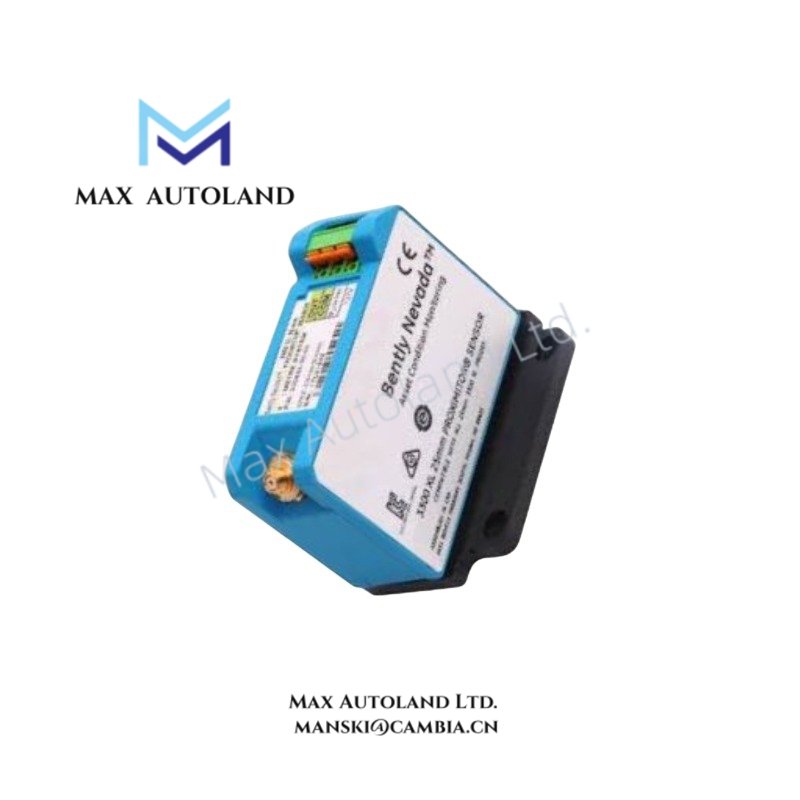
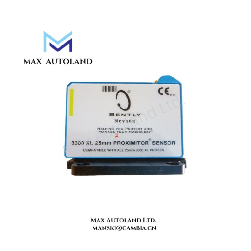


Overview
Suffix Breakdown & Model Matrix
| Code | Description |
|---|---|
| 330850 | 3300 XL 25 mm Proximitor Sensor |
| 50 | 5.0 m (16.4 ft) system length, panel mount |
| CN | Country-specific multiple approvals |
Hardware Specifications
| Parameter | Specification |
|---|---|
| Model | 330850-50-CN |
| Brand | Bently Nevada |
| Product Type | 3300 XL 25 mm Proximitor Sensor |
| Series | 3300 XL |
| Origin | USA |
| Shipping Location | Xiamen, China |
| Weight | 0.2 kg |
| Dimensions | 8.8 x 3.5 x 7 cm (estimated shipping size) |
| Operating Temp | Not specified |
| Power Consumption | Not specified |
| Total System Length | 5.0 m (16.4 ft) |
| Mounting | Panel mount |
| Agency Approval | CN Multiple Approvals |
| Output Resistance | 50 Ohm |
| Average Scale Factor | 0.787 V/mm |
| Probe Case Material | AISI 304 stainless steel |
| Tariff Code | 8537101190 |
Eddy-Current Probe Scaling and Gap Voltage Validation
The 3300 XL 25 mm Proximitor Sensor is designed to operate with compatible eddy-current proximity probes using a calibrated scale factor of 0.787 V/mm. Proper system verification includes gap voltage validation before commissioning. For Bently Nevada eddy-current systems, the probe should normally be adjusted so the static gap voltage falls within the standard operating range centered around -10 VDC according to the applicable probe calibration data. Correct gap adjustment helps maintain linear displacement measurement and minimizes sensitivity variation caused by mechanical installation tolerances.
Frequently Asked Questions
Q: Can the 330850-50-CN be replaced while the monitoring system remains energized?
A: The product documentation supplied does not specify hot-swap capability. Replacement should follow the shutdown and isolation procedure defined for the associated monitoring rack or protection system.
Q: Does the sensor require a specific probe cable length?
A: Yes. This model is configured for a total calibrated system length of 5.0 m (16.4 ft). Probe, extension cable, and Proximitor Sensor should remain within the specified calibrated system configuration.
Q: Why is shield grounding important for this Proximitor Sensor?
A: Proper shield termination reduces electrical noise coupling and limits cross-talk between adjacent proximity measurement channels. Shield grounding should follow the installation practice specified by the monitoring system documentation.
Field Installation Guidelines
- Verify the complete model suffix before installation to ensure the correct system length and approval option.
- Install the panel-mounted housing on a rigid surface to reduce mechanical vibration transfer.
- Route probe cables separately from high-power motor and variable frequency drive wiring whenever practical.
- Maintain cable integrity throughout the calibrated measurement path. Avoid shortening or extending the factory-specified system length.
- Terminate cable shields according to the system grounding philosophy to minimize electromagnetic interference.
- Confirm probe gap voltage after mechanical installation and before placing the machine into continuous operation.






Reviews
There are no reviews yet.