
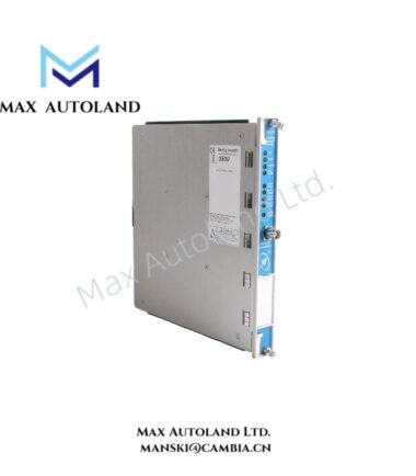
Overview
Suffix Breakdown & Model Matrix
| Parameter | Specification |
|---|---|
| Base Model | 3500/94 |
| Full Configuration | 3500/94M -06-00-00 |
| Module Type | VGA Display Module |
| Display Option | -06 |
| Display Configuration | 15-inch panel-mount VGA display |
| Touch Interface | Resistive touch screen |
| Configuration Status | -00-00 options supplied as part of the stated model configuration |
The supplied information identifies -06 as the 15-inch panel-mount display configuration. The available data does not define additional technical functions for the two -00 option fields; therefore, no unsupported option interpretation is assigned.
Hardware Specifications
| Parameter | Specification |
|---|---|
| Model | 3500/94M -06-00-00 |
| Base Model | 3500/94 |
| Brand | Bently Nevada |
| Product Series | 3500 Machinery Protection System |
| Product Type | VGA Display Module |
| Display Size | 15 inches diagonal |
| Display Resolution | 1024 x 768 pixels |
| Display Format | XGA |
| Touch Technology | Resistive |
| Display Mounting | Panel mount |
| Front Bezel Protection | IP65 |
| Display Power Input | 24 VDC nominal |
| Power Consumption | 4.6 W maximum |
| Communication Port | RS-232 I/O port for touch controller data |
| Front Interface | Front port for configuration and power |
| Operating Temp | -20 deg C to +65 deg C |
| Storage Temp | -40 deg C to +85 deg C |
| Humidity | Up to 95%, non-condensing |
| Hazardous Area Approval | CSA/NRTL/C, Class I, Division 2 |
| EMC Immunity | EN 61000-6-2 |
| EMC Emissions | EN 61000-6-4 |
| Electrical Safety | EN 61010-1 |
| Power Supply Arrangement | Display requires a separate dedicated power supply |
Machinery Monitoring Display Interface
The 3500/94M receives and presents machinery protection information for local operator observation. It can display alarm event lists, system event lists, individual channel values, and rack-oriented monitoring information.
The 15-inch 1024 x 768 display uses a resistive touch interface. Therefore, operators can navigate the main menu and configured user screens directly at the panel.
The supplied configuration supports up to nine user-defined custom screens. These screens can present selected machinery parameters, including vibration-related values and gap measurements, according to the configured monitoring application.
From a TSI perspective, the display itself does not perform eddy-current probe scaling or gap-voltage signal conditioning. Instead, it presents processed information generated by the associated 3500 monitoring hardware. Consequently, probe calibration, -10 VDC gap-voltage validation, and rotor-dynamics calculations remain functions of the relevant monitor channels and transducer circuitry.
The IP65 front bezel provides protection against dust ingress and water jets at the front panel. However, the rating applies to the specified front interface and does not by itself define the environmental rating of the complete installed enclosure.
Frequently Asked Questions (FAQ)
Q: Does the 3500/94M directly condition eddy-current probe signals?
A: No. The 3500/94M provides display and operator-interface functions. Signal conditioning and probe measurement remain within the associated 3500 monitoring modules.
Q: What power does the 3500/94M display require?
A: The supplied specification states 24 VDC nominal display input and 4.6 W maximum power consumption. The display requires a separate dedicated power supply.
Q: What communication interface does the display use for its touch controller?
A: The supplied data specifies an RS-232 I/O port for touch controller data. The front port also supports configuration and power functions.
Field Installation Guidelines
- Verify the complete model and option configuration before installation.
- Confirm that the panel cutout and mounting arrangement match the specified 15-inch panel-mount display.
- Provide the dedicated 24 VDC display power supply specified for the installation.
- Route display power wiring separately from high-energy switching conductors where practical.
- Route RS-232 communication wiring away from strong electromagnetic noise sources.
- Maintain appropriate cable separation from motor, contactor, and high-current power wiring.
- Terminate cable shields according to the site’s EMC grounding standard and the approved 3500 installation practice.
- Ensure the front bezel seats correctly against the panel to maintain the specified front-panel environmental protection.
- Do not obstruct the display ventilation or mechanical mounting surfaces.
- Verify display operation, touch response, communication, and displayed channel values after energization.
- Confirm that alarm and event information corresponds to the configured 3500 monitoring channels before placing the display into service.



Reviews
There are no reviews yet.