
Overview
Hardware Specifications
| Parameter | Specification |
|---|---|
| Model | Bently Nevada 3500/33-SIL2-03-R0 |
| Base Model | 3500/33 |
| Brand | Bently Nevada |
| Manufacturer | Baker Hughes |
| Product Series | 3500 Series |
| Module Type | 16-Channel Relay Output Module |
| Safety Rating | SIL2 |
| Relay Type | SPDT |
| Relay Channels | 16 |
| Contact Type | Low-current gold-plated contacts |
| Minimum Switched Load | 1 mA at 1 VDC |
| Maximum Switched Current | 100 mA at 48 VDC |
| Relay Operation | Normally De-energized or Normally Energized |
| Logic | Programmable AND/OR combinations |
| Power Consumption | 5.8 W typical |
| Rack Space | 1 full-height front slot and 1 full-height rear I/O slot |
| Dimensions | 241 mm x 24.4 mm x 242 mm |
| Weight | 0.7 kg |
Mechanical Protection and Relay Logic
The 3500/33 provides independent relay outputs for external alarm and shutdown circuits. Each channel can operate as Normally De-energized or Normally Energized according to system configuration.
The module supports programmable Alarm Drive Logic. Therefore, relay activation can combine Alert, Danger, Not-OK, and individual measured-variable states through AND/OR logic.
The -03 configuration uses gold-plated relay contacts for low-current switching. It supports loads as low as 1 mA at 1 VDC and switches up to 100 mA at 48 VDC.
For machinery protection applications, the relay logic operates on status information generated by the 3500 rack. Consequently, the module can transfer configured machine-condition states to external control or protection circuits without changing the monitored measurement itself.
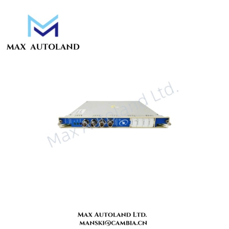
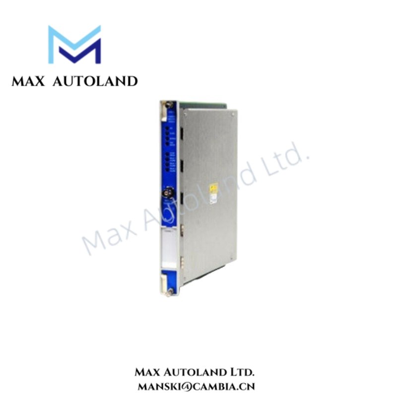
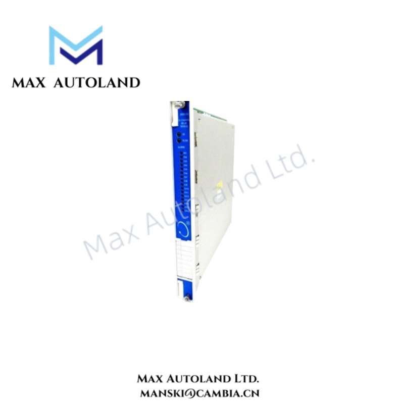
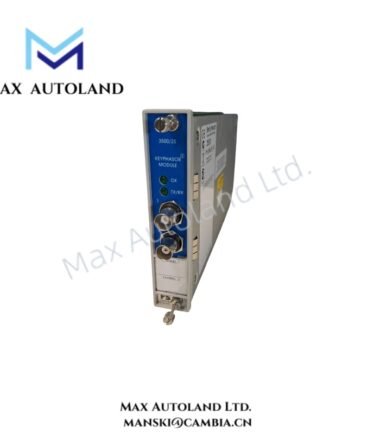
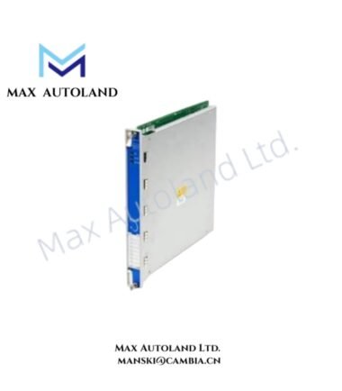
The front panel provides OK, TX/RX, and CH Alarm LEDs. The OK LED indicates module operating status, while TX/RX indicates rack communication activity. The CH Alarm LED indicates an alarm condition on a relay channel.
Frequently Asked Questions
Q: What type of relay contacts does the 3500/33-SIL2-03-R0 use?
A: It uses SPDT relay contacts with gold-plated contacts for low-current switching.
Q: What switching range is specified for the -03 relay configuration?
A: The supplied data specifies a minimum switched load of 1 mA at 1 VDC and a maximum switched current of 100 mA at 48 VDC.
Q: Can relay channels use different operating states?
A: Yes. Programmable relay groups can be configured for Normally De-energized or Normally Energized operation.
Field Installation Guidelines
- Install the module in the designated 3500 rack front slot and install the associated I/O module in the corresponding rear slot.
- Verify rack power isolation before inserting or removing the module.
- Confirm relay wiring against the approved machinery protection logic and terminal assignment documentation.
- Keep low-level relay wiring separated from high-voltage switching conductors and high-current power cables.
- Use appropriate shield termination practices where shielded external signal cables are specified by the system design.
- Verify the external load remains within the specified 1 mA at 1 VDC minimum and 100 mA at 48 VDC maximum switching limits.
- Confirm Normally De-energized or Normally Energized configuration before commissioning.
- Check the OK, TX/RX, and CH Alarm LEDs after installation and verify relay operation through the approved system test procedure.

Reviews
There are no reviews yet.