





Overview
Suffix Breakdown & Model Matrix
The available ordering information identifies the following configured options for 330850-90-CN.
| Suffix | Description |
|---|---|
| 90 | 9.0 metres (29.5 feet) system length, panel mount |
| CN | Country-specific approvals option (refer to the applicable CN Approvals documentation) |
Hardware Specifications
| Parameter | Specification |
|---|---|
| Model | 330850-90-CN |
| Brand | Bently Nevada |
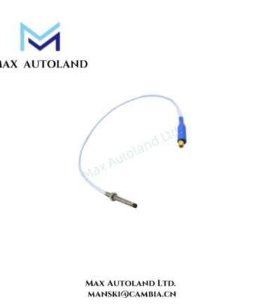
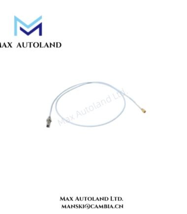
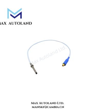
| Product Type | 3300 XL 25 mm Proximitor Sensor |
| Manufacturer | Bently Nevada |
| Origin | USA |
| Shipping Location | Xiamen, China |
| Tariff Code | 8537101190 |
| Total System Length | 9.0 metres (29.5 feet) |
| Mounting Option | Panel mount |
| Probe Tip Material | Polyetheretherketone (PEEK) |
| Proximitor Housing Material | A380 aluminum |
| Agency Approval | CN country-specific approvals |
| Weight | 0.2 kg |
| Dimensions | 8.8 x 3.5 x 7 cm (shipping size) |
| Operating Temp | Not specified |
| Power Consumption | Not specified |
Eddy-Current Signal Scaling and Gap Voltage Validation
The 3300 XL 25 mm Proximitor Sensor is designed for operation with the corresponding eddy-current probe system. Correct probe extension cable length and matched system components should be maintained to preserve calibrated eddy-current scaling. During commissioning, gap voltage validation is commonly performed against the target operating range specified for compatible Bently Nevada proximity measurement systems, including verification near the standard -10 VDC reference region where applicable. Proper cable routing, shield continuity, and separation from high-energy conductors assist in minimizing cross-talk between adjacent vibration channels.
Frequently Asked Questions
Q: Can the Proximitor Sensor be replaced independently of the probe?
A: Replacement should follow the configured system requirements. The probe, extension cable, and Proximitor Sensor are intended to operate as a matched measurement system with the specified total system length.
Q: Is hot swapping recommended while the monitoring system is energized?
A: The supplied documentation does not specify hot-swap capability. Installation or replacement should follow the shutdown and maintenance procedures defined for the associated monitoring system.
Q: What installation practice is recommended for signal cable routing?
A: Route proximity transducer cables separately from power wiring, maintain shield integrity, and avoid parallel runs with high-current conductors to reduce electromagnetic interference.
Field Installation Guidelines
- Confirm that the ordered system length matches the installed probe and extension cable configuration before energizing the channel.
- Mount the Proximitor Sensor on a suitable panel surface using the specified mounting arrangement.
- Maintain continuous cable shielding and apply grounding in accordance with the system installation manual.
- Avoid excessive cable bending, mechanical tension, or compression during installation.
- Verify probe gap voltage after installation before placing the monitored machine into normal operation.
- Confirm that the installed approval option matches the site regulatory requirements before commissioning.






Reviews
There are no reviews yet.