
Overview
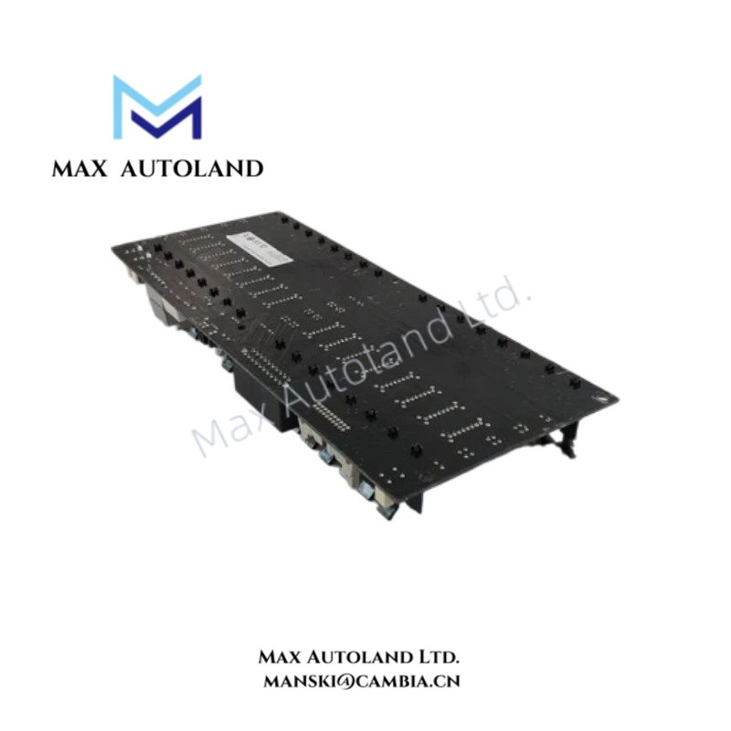
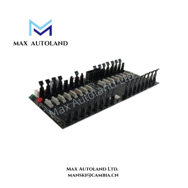
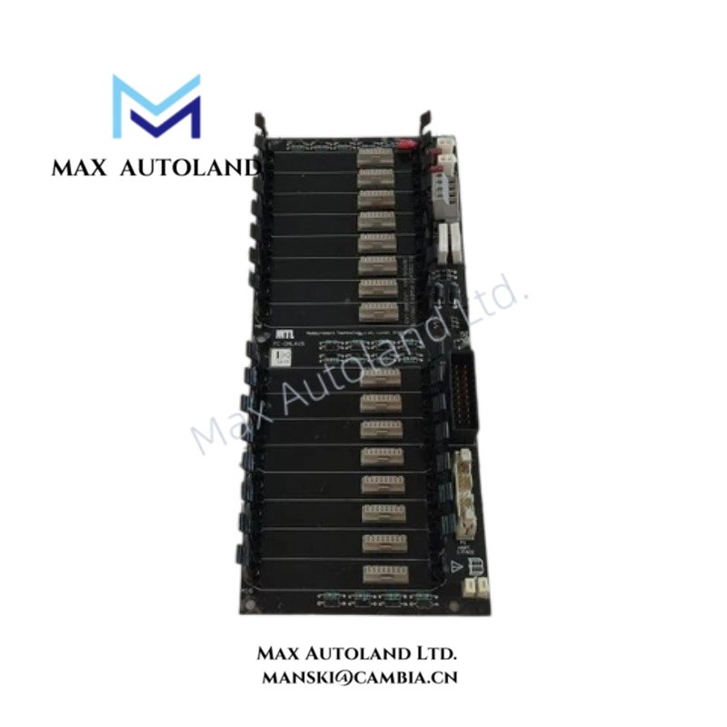
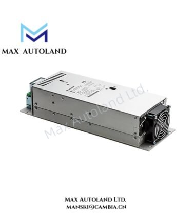
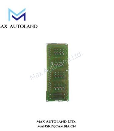
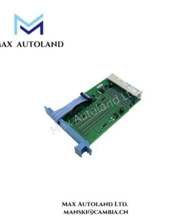
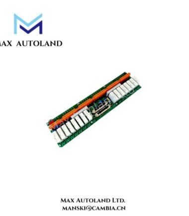
Configured for analog signal acquisition in an industrial control system, the Honeywell FC-GMLA16 (FC-GMLA16 Analog Input Module / FTA) provides direct electrical interfacing for field analog signals. The unit accepts 0-20 mA, 4-20 mA, and 0-10 V inputs across 16 isolated channels and converts the signals into digital measurement data for control-system processing.
Hardware Specifications
| Parameter | Specification |
|---|---|
| Model | FC-GMLA16 |
| Brand | Honeywell |
| Product Type | 16-Channel Analog Input Module / FTA |
| Number of Channels | 16 isolated analog input channels |
| Input Types | 0-20 mA, 4-20 mA, 0-10 V |
| Resolution | 16 bits |
| Accuracy | +/-0.1% FS |
| Sampling Rate | 100 ms per channel |
| Power Supply | 24 VDC |
| Operating Temp | -20 deg C to +60 deg C |
| Storage Temp | -40 deg C to +85 deg C |
| Enclosure Rating | IP67 |
Analog Signal Interface and Channel Isolation
The FC-GMLA16 accepts current and voltage signals from field instrumentation. Each of its 16 input channels is specified as isolated, which separates individual input circuits for field signal acquisition. The module supports 0-20 mA and 4-20 mA current inputs as well as 0-10 V voltage inputs.
The 16-bit resolution provides digital representation of the measured analog signal. In addition, the specified accuracy is +/-0.1% FS. The sampling rate is 100 ms per channel, defining the stated measurement update interval for each input channel.
Frequently Asked Questions
Q: What analog signals can the FC-GMLA16 accept?
A: The supplied specifications list 0-20 mA, 4-20 mA, and 0-10 V input signals.
Q: How many input channels does the FC-GMLA16 provide?
A: The module provides 16 isolated analog input channels.
Q: What power supply does the module require?
A: The supplied data specifies a 24 VDC power supply.
Field Installation Guidelines
Install the module in accordance with the applicable Honeywell system hardware documentation and cabinet requirements. Verify the module identification before wiring.
Separate analog signal wiring from high-voltage power conductors and high-current switching circuits where the installation permits. Use appropriate shielded instrumentation cable for low-level analog signals.
Terminate cable shields according to the system grounding design. Avoid creating unintended ground loops between field devices, signal shields, and control-system grounding points.
Before energizing the module, verify the 24 VDC supply polarity and confirm that each field circuit matches the configured input type. Check current-loop wiring for 0-20 mA or 4-20 mA operation and verify voltage wiring for 0-10 V operation.
Confirm channel assignments against the control-system configuration before commissioning. Do not apply a voltage signal to a channel wired for a current loop unless the system documentation specifies that configuration.





Reviews
There are no reviews yet.