
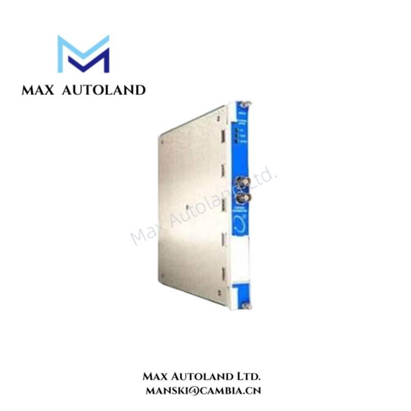

Overview
Hardware Specifications
| Parameter | Specification |
|---|---|
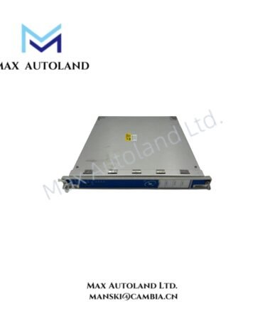
| Model | 3500/91-01-02-02 |
| Base Model | 3500/91 |
| Brand | Bently Nevada |
| Product Type | EGD Communication Gateway Module |
| System | 3500 Machinery Protection System |
| Communication Protocol | EGD version 2.01, Ethernet UDP/IP |
| Ethernet Standard | IEEE 802.3, IEEE 802.3u |
| Ethernet Speed | 10/100 Mbps |
| Power Consumption | 7.4 Watts typical |
| Main Module Dimensions | 241.3 mm x 24.4 mm x 241.8 mm |
| Main Module Weight | 0.79 kg |
| I/O Module Dimensions | 241.3 mm x 24.4 mm x 99.1 mm |
| I/O Module Weight | 0.39 kg |
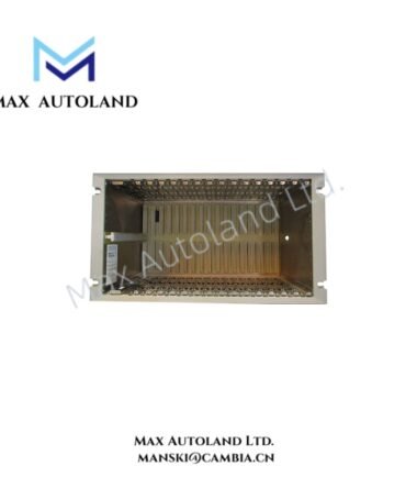
| Rack Space | Main module: 1 full-height front slot; I/O module: 1 full-height rear slot |
| Operating Temperature | -30 deg C to +65 deg C |
| Storage Temperature | -40 deg C to +85 deg C |
| Humidity | Up to 95%, non-condensing |
| Status Indicators | OK LED, TX/RX LED |
| Producer Data | Rack, module, channel, overall status, real-time values, configured setpoints |
| Consumer Commands | Group Reset, Group Trip Multiply, Group Alarm Inhibit, Group Special Alarm Inhibit |
Bently Nevada Machinery Monitoring and Data Exchange
The 3500/91 transfers monitored rack information from the machinery protection system to an external Ethernet-based control platform. Producer exchanges can include vibration and process-variable values in floating-point format, together with rack, module, channel, and overall status information.
Conversely, consumer exchanges allow the external system to transmit defined control functions, including Group Reset, Group Trip Multiply, Group Alarm Inhibit, and Group Special Alarm Inhibit.
The Ethernet interface operates at 10/100 Mbps and follows IEEE 802.3 and IEEE 802.3u standards. Therefore, network configuration must maintain the required Ethernet physical-layer conditions and appropriate separation from electrically noisy field wiring.
For Bently Nevada machinery monitoring systems, field verification should also distinguish communication faults from probe-system faults. Where eddy-current proximity measurements are involved, technicians should validate probe scaling, target geometry, and gap voltage independently before diagnosing the 3500/91 communication path. A nominal -10 VDC gap-voltage target is commonly used for Bently Nevada proximity probe systems, but the exact operating target must follow the applicable probe and transducer documentation.
Frequently Asked Questions
Q: What Ethernet protocols does the 3500/91-01-02-02 support?
A: The module supports EGD version 2.01 and Ethernet UDP/IP communication. The interface conforms to IEEE 802.3 and IEEE 802.3u and supports 10/100 Mbps operation.
Q: What data can the module transmit from the 3500 rack?
A: Producer exchanges can contain rack, module, channel, and overall status information, real-time vibration and process-variable values, and configured system setpoints.
Q: Does the module receive commands from an external control system?
A: Yes. Consumer exchanges support Group Reset, Group Trip Multiply, Group Alarm Inhibit, and Group Special Alarm Inhibit functions.
Field Installation Guidelines
- Install the main communication module in the designated full-height front rack slot and the associated I/O module in the designated rear slot.
- Confirm the module seating and connector engagement before energizing the 3500 rack.
- Route Ethernet communication wiring separately from high-current power conductors and strong electromagnetic noise sources where practical.
- Maintain proper cable shielding and grounding practices according to the installed Ethernet hardware and site grounding design.
- Verify Ethernet link status using the front-panel TX/RX indication after network connection.
- Check the OK LED before commissioning data exchanges.
- Confirm EGD configuration, UDP/IP addressing, and external controller data mapping before enabling operational commands.
- Test producer data independently from consumer commands during commissioning.
- If machinery values appear incorrect, verify the upstream transducer chain before attributing the fault to the communication gateway.
- For proximity measurement channels, verify probe installation, cable connections, target condition, and gap voltage according to the applicable 3500 system documentation.
- Do not apply consumer commands during commissioning until the external control logic and command mapping have been validated.



Reviews
There are no reviews yet.