


Overview
Suffix Breakdown & Model Matrix
| Parameter | Specification |
|---|---|
| Base Model | 3500/05 |
| Full Model | 3500/05-01-02-CN-00-01 |
| Rack Size Code | -01, 19-inch full-size rack |
| Mounting Code | -02, rack mount configuration |
| Agency Approval Code | -CN, China regional approval configuration |
| Internal Barrier Code | -00, no internal barriers |
| European Compliance Code | -01, CE compliance |
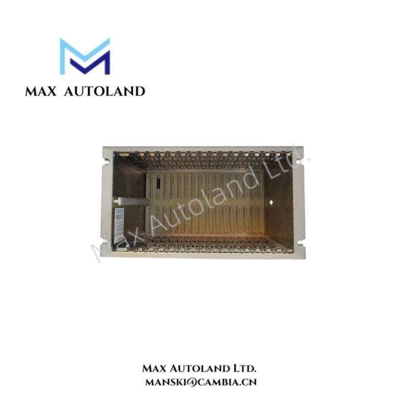
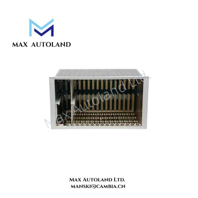
| Module Capacity | 14 available monitor module slots, excluding power supply and RIM positions |
Hardware Specifications
| Parameter | Specification |
|---|---|
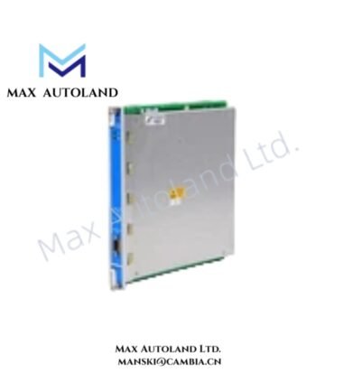
| Model | 3500/05-01-02-CN-00-01 |
| Brand | Bently Nevada |
| Product Series | 3500 Machinery Protection System |
| Product Type | System Rack |
| Dimensions | Approx. 133.35 mm H x 482.60 mm W front profile; depth not specified |
| Operating Temp | Not specified in the supplied data |
| Power Consumption | Determined by installed power supplies and rack modules; rack consumption not specified |
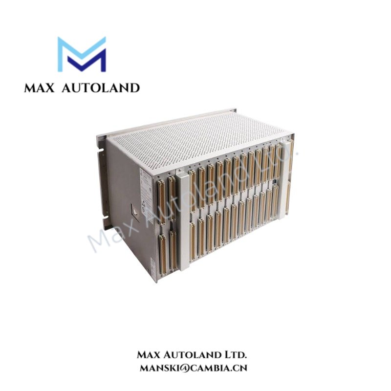
| Rack Format | 19-inch EIA full-size rack |
| Mounting | Rack mount |
| Module Slots | 14 available monitor module slots |
| Power Supply Positions | Reserved rack positions |
| RIM Position | Reserved rack position |
| Backplane | Provides internal module communication and power distribution |
| Construction | Industrial metallic rack housing |
| Internal Barriers | None |
| Regional Configuration | China regional approval configuration |
| European Compliance | CE |
Machinery Protection Integration
The 3500/05 rack provides the physical and electrical infrastructure for monitor modules that process machinery-condition signals. Consequently, the rack itself does not perform vibration measurement or probe signal conditioning; installed monitor modules perform those functions.
Bently Nevada 3500 monitor channels can interface with eddy-current proximity systems and other machinery transducers. During commissioning, technicians should validate probe installation, signal scaling, and gap voltage at the applicable monitor or transducer interface.
For eddy-current measurement systems, a nominal probe gap target of approximately -10 VDC is commonly used during setup when the associated transducer system specifies this condition. However, the exact target must follow the installed probe and monitor configuration.
The rack backplane also provides the internal connection path between installed modules, power supplies, and the RIM. Therefore, correct module placement and full engagement with the backplane remain necessary for normal rack operation.
Frequently Asked Questions (FAQ)
Q: Does the 3500/05 rack itself measure vibration or shaft position?
A: No. The rack provides mounting, power distribution, and backplane communication. Dedicated 3500 monitor modules perform signal conditioning and machinery measurement.
Q: How many monitor module positions does the full-size rack provide?
A: The supplied specification identifies 14 available monitor module slots, with separate positions reserved for power supplies and the RIM.
Q: Can the rack determine the correct eddy-current probe gap voltage?
A: No. Gap voltage depends on the installed probe, extension cable, Proximitor interface, and monitor configuration. Technicians should verify the specified gap condition at the applicable measurement circuit.
Field Installation Guidelines
- Install the rack in a standard 19-inch EIA-compatible cabinet or enclosure with adequate mechanical support.
- Secure the rack using the designated rack mounting points. Confirm that the chassis remains mechanically aligned before inserting modules.
- Verify that power supply and RIM positions remain correctly allocated according to the 3500 rack configuration.
- Inspect the backplane connectors before installation. Do not force a module into position if connector alignment is incorrect.
- Route transducer and signal wiring separately from high-current power conductors where practical to reduce electromagnetic interference.
- Maintain appropriate cable shielding and grounding practices according to the installed Bently Nevada transducer and monitor configuration.
- For eddy-current channels, verify probe polarity, extension cable connections, signal scaling, and gap voltage before placing the machinery protection channel into service.
- Confirm that all installed monitor modules match the configured rack architecture and system documentation before energizing the rack.
- After installation, verify module seating, power supply status, RIM communication, and rack-level diagnostic indications.









Reviews
There are no reviews yet.