
Overview
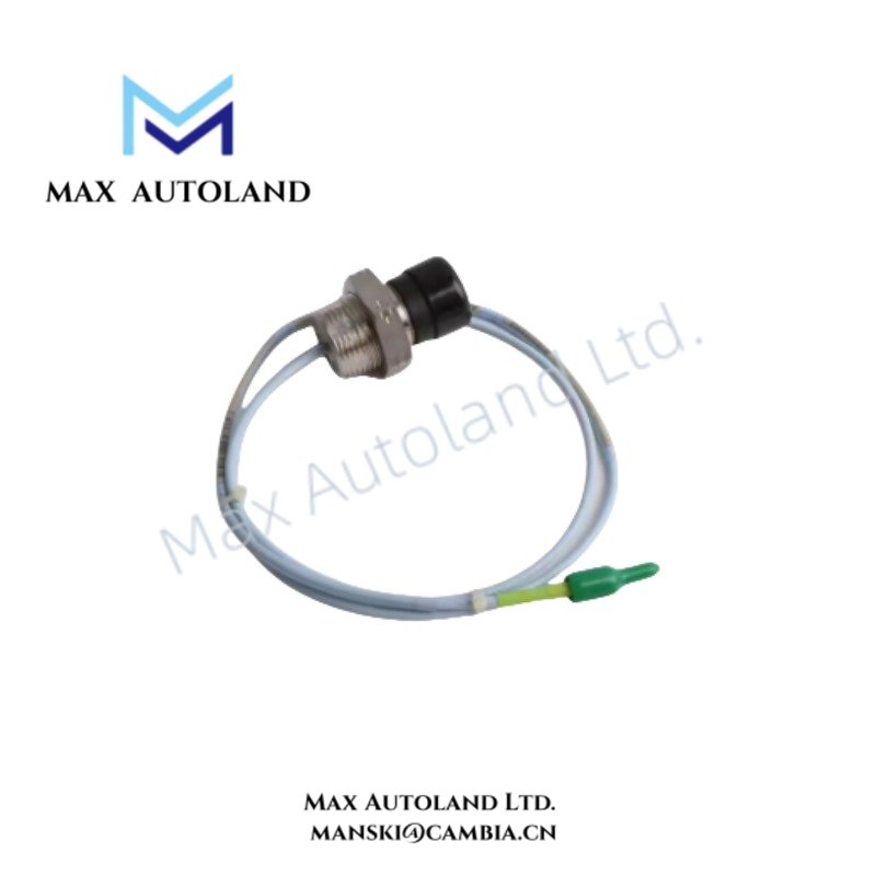
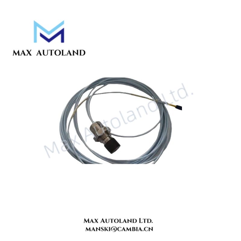
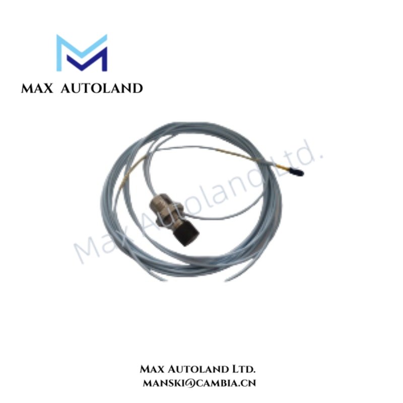
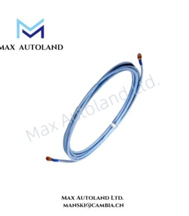
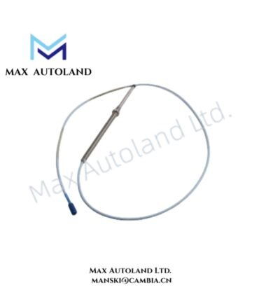
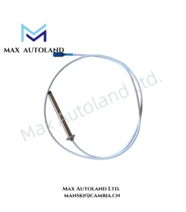
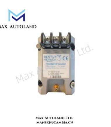
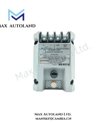
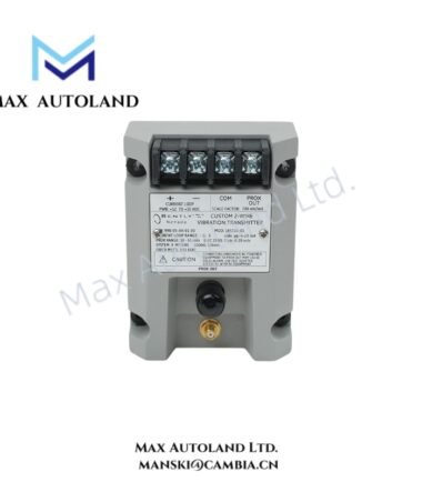
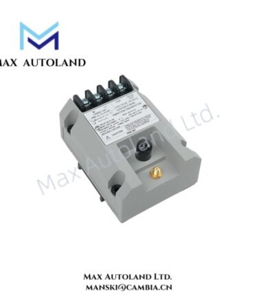
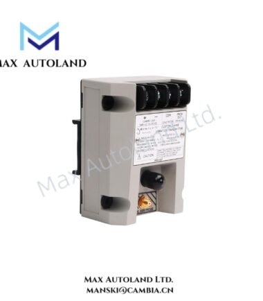
Configured for shaft displacement measurement in Bently Nevada 3300 XL TSI monitoring systems, the Bently Nevada 330851-02-000-060-10-00-CN (330851 3300 XL 25 mm Proximity Probe) provides direct physical signal detection through eddy-current sensing technology.
Hardware Specifications
| Parameter | Specification |
|---|---|
| Model | 330851-02-000-060-10-00-CN |
| Brand | Bently Nevada |
| Product Type | 3300 XL 25 mm Proximity Probe |
| Origin | USA |
| Weight | 0.23 kg |
| Dimensions | Overall case length: 60 mm; total cable length: 1.0 m |
| Power Consumption | Passive eddy-current probe; powered by compatible proximity system driver |
| Probe Case Type | Option 02: M30x2 thread |
| Unthreaded Length | Option 000: 0 in |
| Overall Case Length Option | 060: 60 mm |
| Total Length Option | 10: 1.0 metre (3.3 feet) |
| Armor Option | 00: No armor |
| Agency Approval Option | CN: Country-specific approvals |
Eddy-Current Probe Scaling and Rotor Dynamics Measurement
The 3300 XL 25 mm Proximity Probe uses eddy-current measurement principles to convert shaft movement into an electrical displacement signal. The probe operates with a compatible Bently Nevada proximity system driver that provides excitation, demodulation, and signal conditioning.
Furthermore, the probe supports rotor dynamics analysis by measuring relative shaft position changes, vibration amplitude, and mechanical movement. The system evaluates probe output together with gap voltage conditions, where a typical operating reference uses gap voltage validation with -10 VDC targets for correct probe positioning.
The probe design maintains measurement consistency through controlled electromagnetic characteristics. In addition, the sensing face geometry and M30x2 threaded case configuration support stable mechanical installation near rotating components.
Frequently Asked Questions
Q: What measurement principle does the 330851-02-000-060-10-00-CN use?
A: The probe uses eddy-current sensing technology to detect relative shaft displacement and provide an electrical output signal through a compatible Bently Nevada proximity system.
Q: Does this probe include an armored cable option?
A: No. The supplied model configuration uses armor option 00, which specifies no armor.
Q: What should be checked during probe installation?
A: Technicians should verify probe thread engagement, target surface condition, cable routing, electrical shielding, and gap voltage alignment before placing the monitoring system into operation.
Field Installation Guidelines
Install the probe with the specified M30x2 threaded connection and maintain proper mechanical alignment with the monitored shaft surface.
Route the extension cable and signal cable away from high-current power conductors to reduce electromagnetic interference. Use appropriate shielding and grounding practices according to the monitoring system installation requirements.
Before operation, verify the probe gap position through the connected proximity system. Confirm that the electrical output corresponds with the expected shaft position reference and that the probe tip remains free from mechanical contact.
Avoid sharp cable bends and excessive mechanical stress on the cable termination area. Secure the cable along the installation path to prevent vibration-induced movement.



Reviews
There are no reviews yet.