
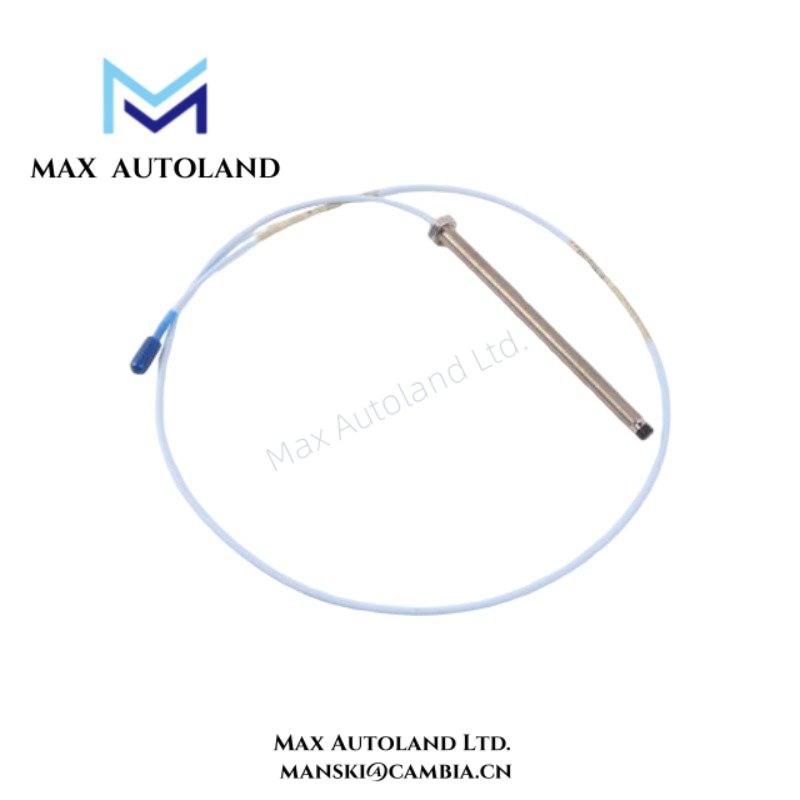

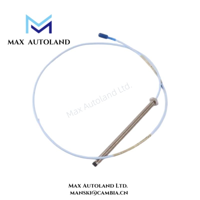
Overview
Suffix Breakdown & Model Matrix
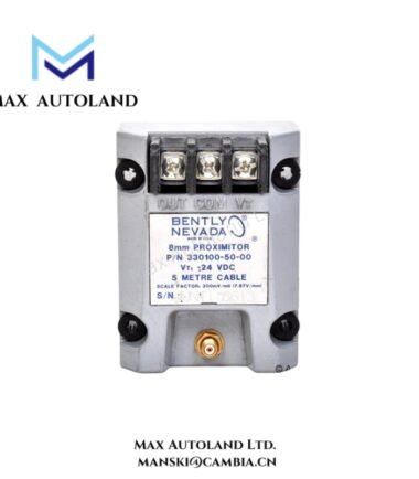
The supplied documentation identifies 330103-00-05-10-01-00 as a fixed ordering configuration within the Bently Nevada 3300 XL 8 mm proximity transducer family. No additional suffix matrix decomposition is defined in the provided source material.
Specifications
| ParameterSpecification | |
| Model | 330103-00-05-10-01-00 |
| Brand | Bently Nevada |
| Origin | USA |
| Product Series | 3300 XL 8 mm |
| Device Type | Proximity Transducer / Proximity Sensor |
| Measurement Principle | Eddy-current non-contact displacement sensing |
| Probe Diameter | 8 mm |
| Application Function | Shaft vibration, axial position, and gap measurement |
| System Compatibility | Bently Nevada 3300 XL transducer systems |
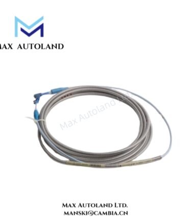
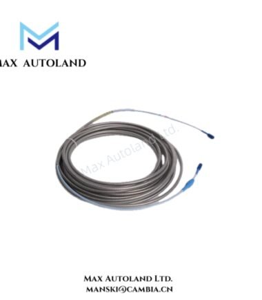
| Signal Interface | Requires matched extension cable and compatible driver |
| Operating Target | Conductive metallic machine target surface |
| Weight | Not specified in provided documentation |
| Dimensions | Configuration dependent; exact values not specified |
| Operating Temp | Refer to configured system component ratings |
| Power Consumption | Dependent on associated driver electronics |
Eddy-Current Scaling and Gap Voltage Behavior
The 3300 XL 8 mm transducer operates inside rotor dynamic measurement loops; therefore, probe scaling depends on electrical matching across the probe, extension cable, and signal conditioner. During commissioning, technicians typically verify gap voltage to confirm both mechanical spacing and sensor operating status. In many installations, acceptable behavior includes negative DC bias conditions near the expected -10 VDC region. However, incorrect probe clearance, incompatible target metallurgy, or cable mismatch can shift bias response outside the intended operating window. In parallel monitoring channels, proper cable spacing, intact shielding, and controlled routing further reduce signal coupling and suppress cross-talk between adjacent vibration circuits.
Frequently Asked Questions
Q: Can the transducer connect directly to a PLC analog input module?
A: No. The probe requires compatible signal conditioning hardware that supplies excitation, scaling, and calibrated response characteristics. A standard PLC analog input channel does not provide those functions.
Q: Does probe replacement require post-installation verification?
A: Yes. After replacement, technicians typically confirm component matching, observe signal behavior, and validate gap voltage response before returning the machine train to monitored operation.
Q: Do cable routing practices influence measurement quality?
A: Yes. Routing probe wiring close to motor feeders, VFD output conductors, or switching power circuits can introduce electrical interference into low-level sensing paths.
Field Installation Guidelines
Mount the probe in a rigid mechanical assembly and maintain controlled alignment with the conductive target surface. Next, route transducer wiring separately from power cables, contactor wiring, and high-current switching conductors. Apply shield grounding according to the applicable installation standard, and avoid uncontrolled multi-point shield termination. Before startup, inspect connector integrity, verify mounting security, and confirm expected gap voltage behavior under installed machine conditions.



Reviews
There are no reviews yet.