
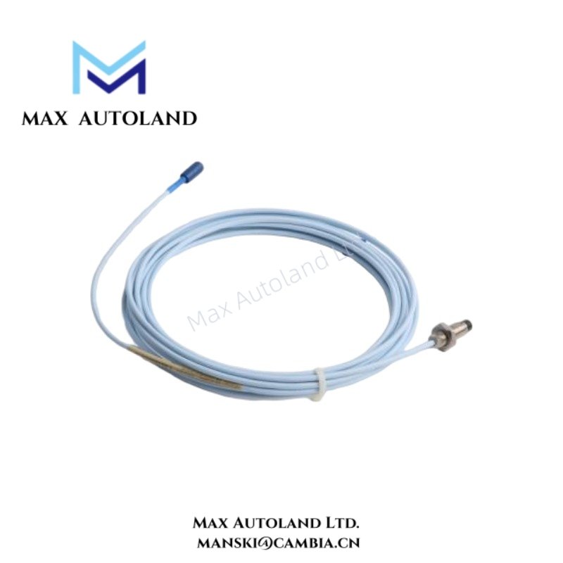
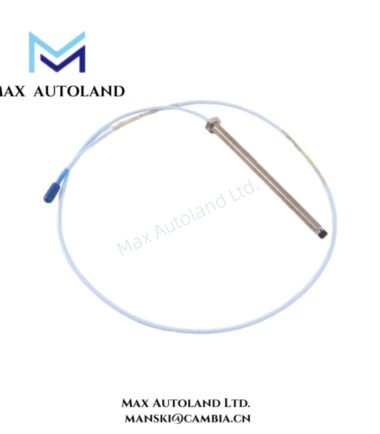
Overview
Suffix Breakdown & Model Matrix
The supplied references identify 330103-00-03-50-02-00 as a fixed configured model within the 3300 XL 8 mm product family. The source material does not provide an official suffix decoding matrix. Configuration interpretation should therefore follow manufacturer ordering documentation.
Specifications
| ParameterSpecification | |
| Model | 330103-00-03-50-02-00 |
| Brand | Bently Nevada |
| Origin | USA |
| Product Type | Proximity Transducers |
| Series | 3300 XL 8 mm |
| Probe Diameter | 8 mm |
| Measurement Principle | Eddy-current non-contact sensing |
| Functional Role | Shaft vibration, axial position, and displacement monitoring |
| System Compatibility | Bently Nevada 3300 XL transducer systems |
| Target Material | Electrically conductive metallic targets |
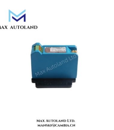
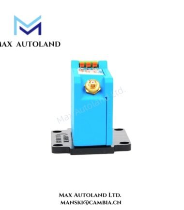
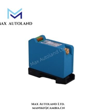
| Signal Chain Requirement | Matched probe, extension cable, and compatible Proximitor electronics |
| Output Characteristic | Electrical response proportional to target displacement |
| Mounting Method | Threaded mechanical installation |
| Weight | Not explicitly specified |
| Dimensions | Refer to manufacturer dimensional documentation |
| Operating Temp | Refer to official Bently Nevada environmental specification |
| Power Consumption | Determined by associated signal conditioning electronics |
Rotor Dynamics and Cross-Talk Suppression
The 3300 XL 8 mm proximity transducer operates within rotor dynamic monitoring loops that require stable probe response and controlled electrical behavior. To maintain signal consistency, users must preserve the matched relationship between the probe, extension cable, and driver electronics.
During commissioning, technicians commonly perform gap voltage validation to confirm probe position and target interaction. In typical Bently Nevada proximity systems, engineers compare measured bias response with expected negative DC operating regions, including values near -10 VDC targets. When measured conditions fall outside the expected range, maintenance personnel should inspect probe clearance, conductive target condition, mounting geometry, and cable configuration.
In addition, multi-channel measurement layouts require disciplined wiring practices. Proper cable spacing, shield continuity, and isolated routing paths reduce cross-talk between adjacent sensing channels and support stable vibration signal acquisition.
Frequently Asked Questions
Q: Can the probe connect directly to a PLC analog input module?
A: No. The probe requires compatible signal conditioning electronics that provide excitation and calibrated transducer behavior. Standard PLC analog inputs do not supply these functions.
Q: Can technicians replace the probe without changing the associated cable or electronics?
A: Technicians can perform replacement according to the installed configuration; however, they should verify matched component compatibility, signal behavior, and gap voltage condition after installation.
Q: Do shielding and cable routing practices affect measurement quality?
A: Yes. When installers route sensing cables near switching circuits, motor feeders, or drive output conductors, electrical interference can affect low-level transducer signals.
Field Installation Guidelines
Install the probe with rigid mechanical support and controlled alignment to the conductive target surface. Also, maintain the configured sensing clearance required by the installed transducer arrangement.
Next, route probe wiring separately from power conductors, switching circuits, and variable-frequency drive output cables. Apply shield grounding according to the site grounding standard, and avoid uncontrolled multi-point shield connections. Finally, verify connector integrity, mounting condition, and measured gap voltage response before returning the monitored equipment to operation.






Reviews
There are no reviews yet.