
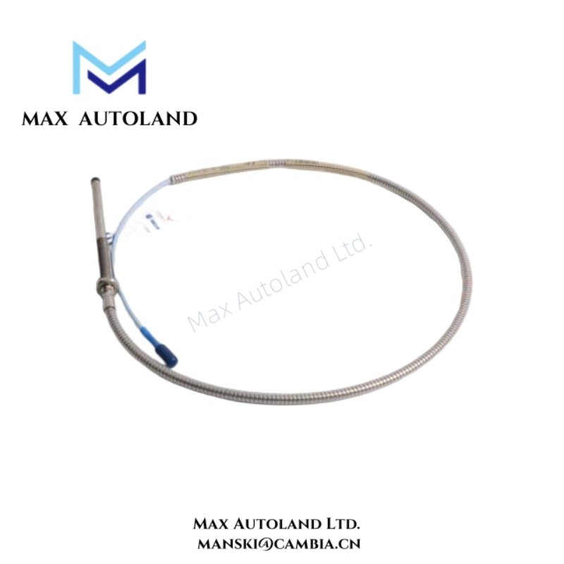
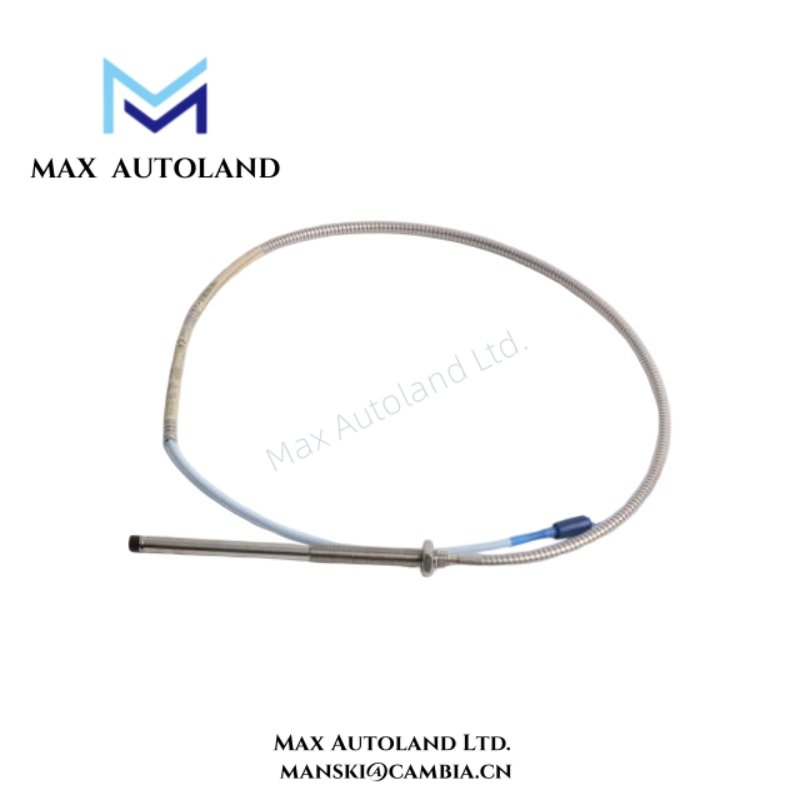
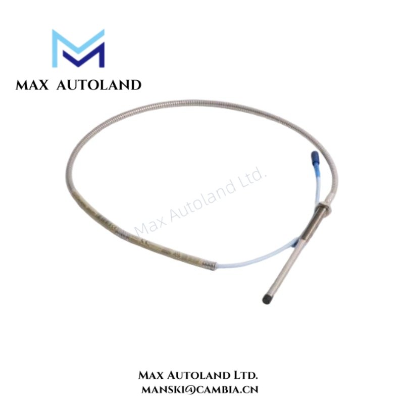
Overview
Specifications
| ParameterSpecification | |
| Model | 330104-00-08-10-02-CN |
| Brand | Bently Nevada |
| Origin | USA |
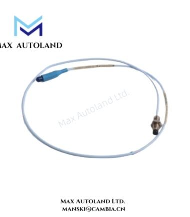
| Product Series | 3300 XL 8 mm |
| Device Type | Proximity Transducer |
| Measurement Principle | Eddy-current non-contact sensing |
| Probe Diameter | 8 mm |
| Sensing Function | Shaft vibration, axial position, and gap measurement |
| System Compatibility | Bently Nevada 3300 XL Transducer System |
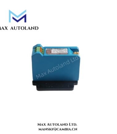
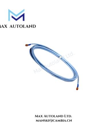
| Electrical Configuration | Requires matched probe, extension cable, and Proximitor sensor |
| Target Material | Conductive metallic target surface |
| Weight | Not specified in supplied documentation |
| Dimensions | Configuration dependent; exact values not specified |
| Operating Temp | Refer to installed component ratings |
| Power Consumption | Determined by associated signal conditioning electronics |
Rotor Dynamics and Gap Voltage Validation
The 3300 XL 8 mm proximity transducer operates inside rotor dynamic monitoring loops; therefore, signal scaling depends on preserved electrical matching between probe, cable, and driver sections. During commissioning, technicians commonly verify gap voltage because this check confirms both target spacing and sensor operating condition. In standard Bently Nevada practice, expected behavior includes negative DC bias regions near -10 VDC target values. However, incorrect probe clearance, unsuitable target metallurgy, or incompatible cable configuration can shift the measured response outside the calibrated range. In addition, multi-channel installations require disciplined cable routing, continuous shielding, and physical cable separation to suppress cross-talk between adjacent vibration measurement paths.
Frequently Asked Questions
Q: Can the proximity probe connect directly to a PLC analog input module?
A: No. The sensing element requires compatible signal conditioning electronics that provide excitation, calibration, and defined transducer scaling. Standard PLC analog inputs do not supply these functions.
Q: Does probe replacement require system verification after installation?
A: Yes. Technicians typically check signal response, confirm matched component compatibility, and validate gap voltage condition after replacing a probe assembly.
Q: Does cable routing affect low-level sensing stability?
A: Yes. Routing transducer wiring near motor feeders, switching devices, or variable-frequency drive conductors can introduce unwanted electrical noise into the measurement loop.
Field Installation Guidelines
Install the probe in a rigid mounting arrangement and maintain controlled alignment with the conductive target surface. Next, route transducer wiring separately from power distribution cables, switching circuits, and high-current conductors. Apply shield grounding according to the applicable installation practice, and avoid uncontrolled multi-point shield terminations. Before machine startup, inspect connector integrity, confirm mechanical mounting condition, and verify measured gap voltage response under installed operating geometry.



Reviews
There are no reviews yet.