
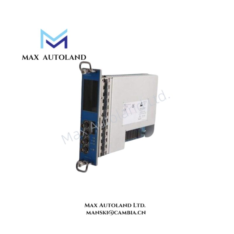
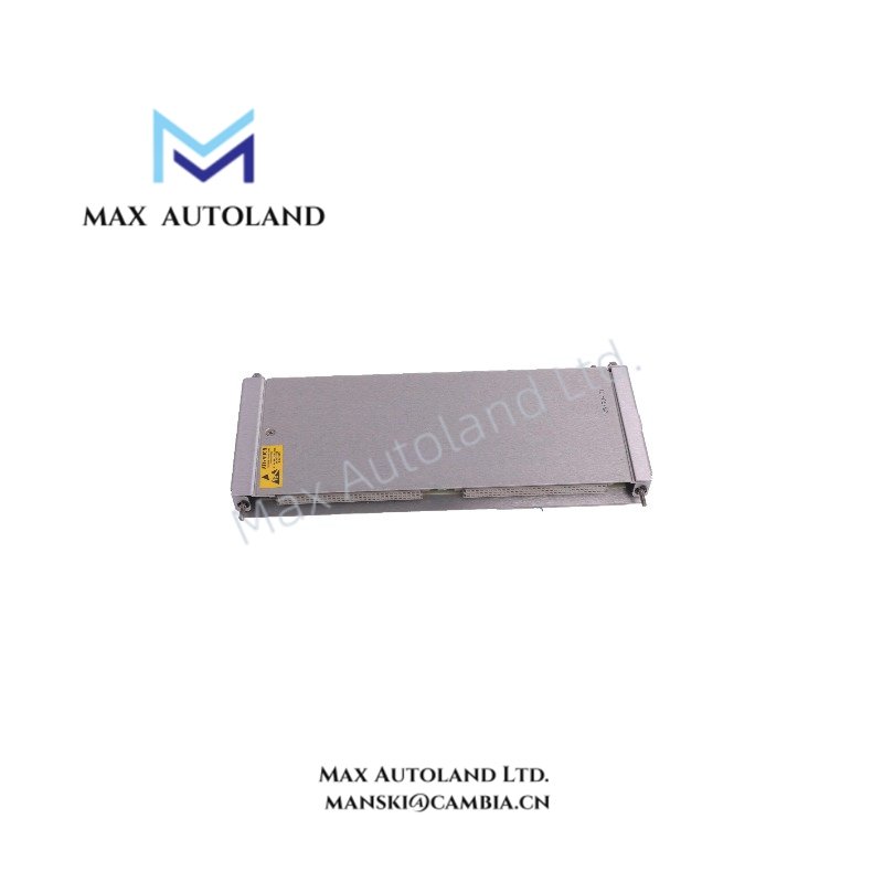
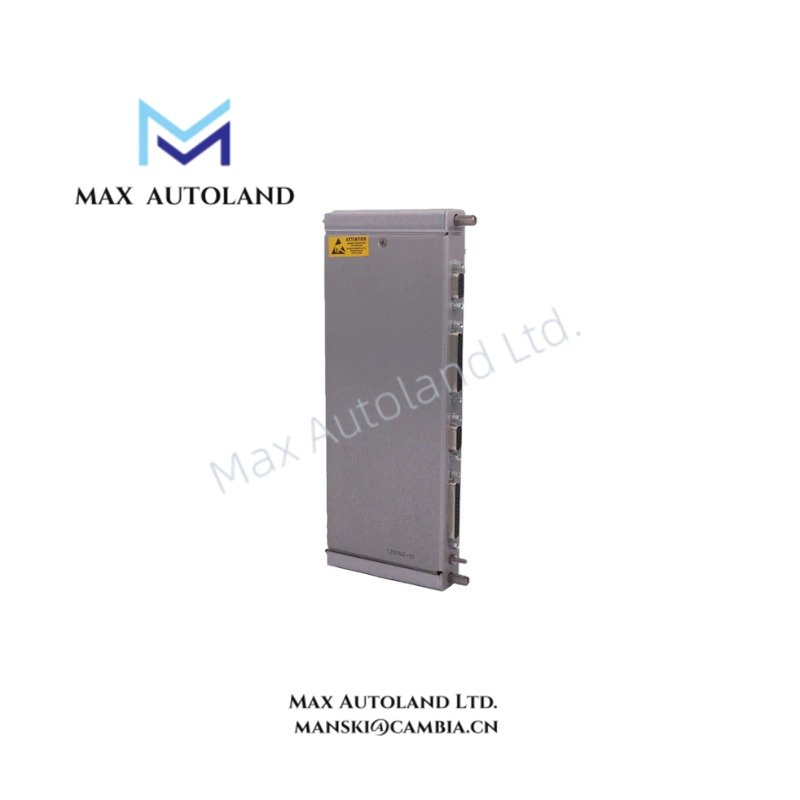
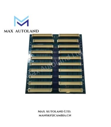
Overview
Suffix Breakdown & Model Matrix
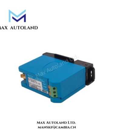
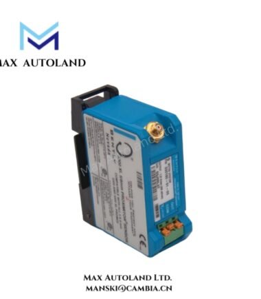
Model: 284398-01
Suffix “-01”: Factory revision / configuration identifier
No further validated segmentation data available in provided documentation.
Hardware Specifications
| Parameter | Specification |
|---|---|
| ModelBrand | Bently Nevada 284398-01 |
| Origin | USA |
| Weight | 0.22 kg |
| Dimensions | 8.8 cm x 3.5 cm x 7 cm |
| OperatingTemp | -40 degC to +85 degC |
| PowerConsumption | Up to 2.5 W (max, typical module class) |
| Input Type | Proximity probe (3300 NSv compatible) |
| Output Signal | 4-20 mA analog current loop |
| Supply Voltage | 18-32 VDC |
| Measurement Function | Thrust / displacement signal conversion |
Eddy-Current Probe Scaling and Gap Voltage Validation Domain (Bently Nevada TSI Binding)
The module processes eddy-current probe inputs with scaling referenced to calibrated gap voltage behavior. Signal conditioning logic aligns probe linear region conversion against standard TSI reference targets, including negative bias validation around -10 VDC nominal gap response regions. Cross-talk suppression is implemented at the analog front-end to minimize channel coupling effects in multi-probe rotor monitoring architectures. This ensures stable conversion integrity under high vibration density environments and shaft displacement transients.
Frequently Asked Questions
Q: Can the module interface directly with 3300 NSv proximity systems?
A: Yes. The input stage is designed for compatibility with 3300 NSv proximity probe and extension cable assemblies, supporting standard eddy-current displacement measurement chains.
Q: What is the output scaling method for the 4-20 mA loop?
A: Output is generated via internal signal conditioning and linear mapping of measured thrust or displacement range into a proportional 4-20 mA current loop for PLC or DCS input.
Q: Does the module support hot-swap replacement in live systems?
A: Hot-swap capability is not explicitly defined. Replacement should follow controlled shutdown or isolation procedures to prevent transient loop disturbances.
Field Installation Guidelines
Ensure proper shield termination at a single-point ground to minimize induced noise on the proximity probe cable. Maintain separation between signal wiring and high-voltage conductors to reduce electromagnetic coupling. Verify loop power stability in the 18-32 VDC range before commissioning. Probe extension cables should be installed without tight bending radius constraints to avoid impedance variation in the eddy-current measurement path.


Reviews
There are no reviews yet.