
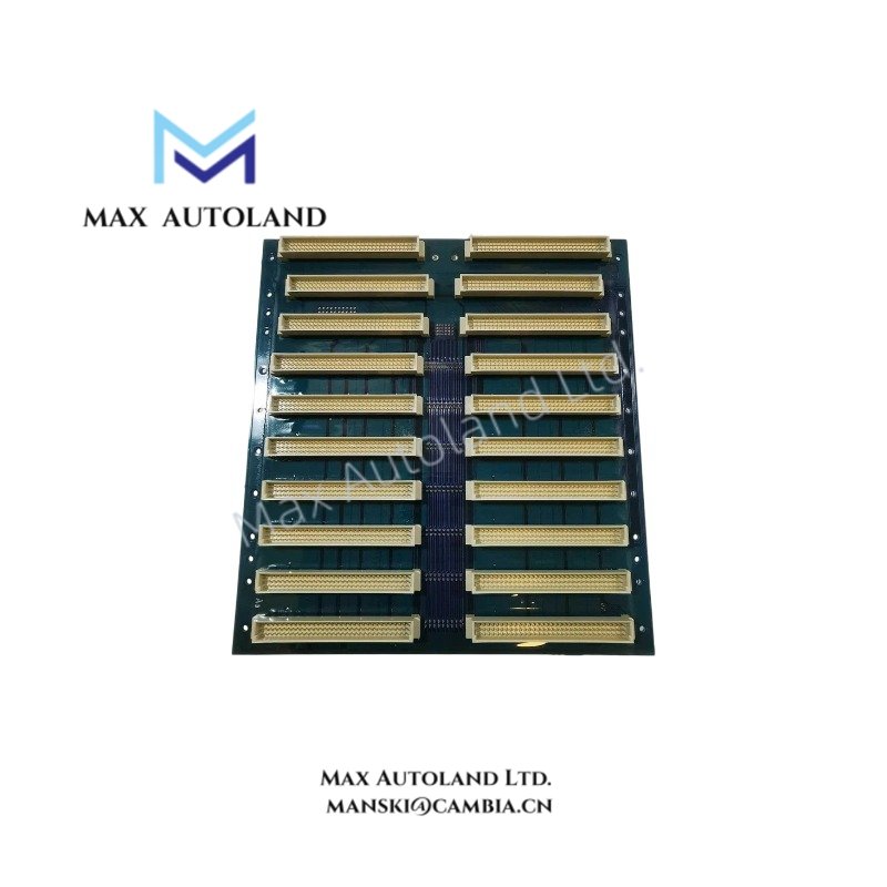
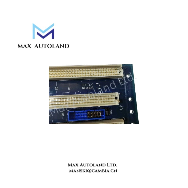
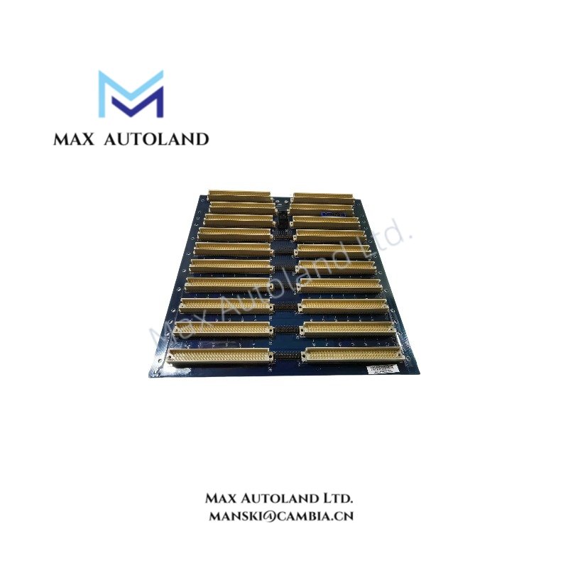


Overview
Hardware Specifications
| Parameter | Specification |
|---|---|
| ModelBrand | Bently Nevada 144464-01 |
| Origin | USA |
| Weight | Approx. 1.0–2.8 kg (configuration dependent) |
| Dimensions | Approx. 305 mm rack width class |
| OperatingTemp | -40 degC to +70 degC |
| PowerConsumption | Not specified (depends on installed modules and system load) |
| System Capacity | Up to 7 module slots (mini-rack configuration) |
| Function | Backplane bus, power distribution, module communication routing |
| Compatibility | Bently Nevada 3500 Series monitoring system |
Eddy-Current Probe Scaling and Signal Integrity Alignment
Within Bently Nevada 3500 architecture, backplane routing stability directly impacts eddy-current probe scaling accuracy and gap voltage validation processes (typical -10 VDC reference target domain). The 144464-01 maintains fixed impedance routing paths across module slots, reducing cross-talk propagation between adjacent measurement channels. This supports consistent signal phase alignment for rotor dynamics monitoring chains where multiple vibration and position inputs share a common rack-level communication backbone.
Frequently Asked Questions
Q: Does the 144464-01 backplane support hot-swap of monitoring modules?
A: Hot-swap capability is defined by the installed 3500 system modules. The backplane itself provides passive electrical routing; insertion/removal behavior depends on module design.
Q: How is power distributed across the rack slots?
A: Power is distributed via integrated backplane bus rails from the system power supply module. Current loading is shared across slot groups based on rack configuration.
Q: Does the backplane introduce signal latency between modules?
A: The backplane operates as a passive interconnect; communication timing is governed by the 3500 system modules and internal bus arbitration, not by active processing on the backplane.
Field Installation Guidelines
Install the backplane into the designated 3500 mini-rack chassis using standard rail alignment points. Ensure all module connectors are fully seated to maintain continuous bus continuity across slots. Maintain separation between signal wiring and high-energy conductors to reduce electromagnetic coupling into the rack interface.
Shield termination should be referenced to a single-point ground within the cabinet to avoid ground loop formation across measurement channels. Verify mechanical fixation torque on rack mounting points according to enclosure specifications. Do not apply external voltage to backplane connectors; all electrical interaction must occur through approved system modules.





Reviews
There are no reviews yet.