
Overview
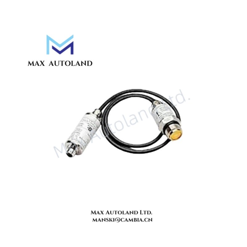
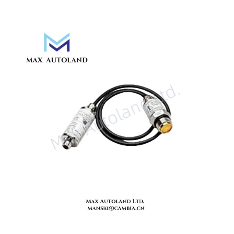
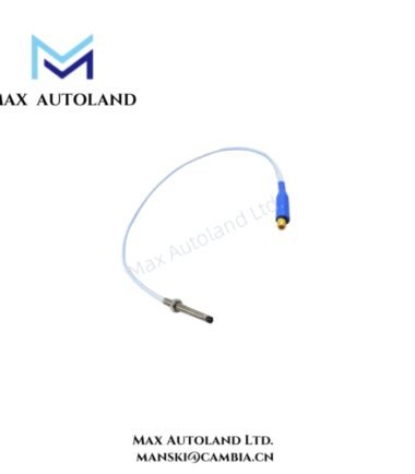
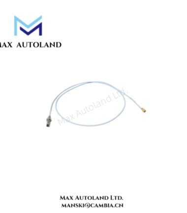
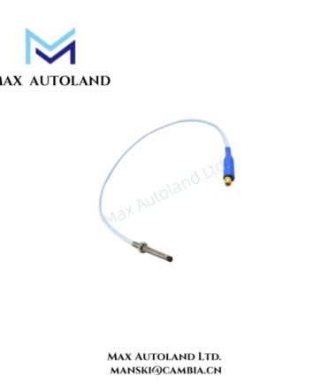
The device operates as an eddy-current sensing element, converting gap variations between probe tip and conductive target surface into proportional electrical signal changes for downstream TSI processing modules.
Hardware Specifications
| Parameter | Specification |
|---|---|
| Model | 165844-14 |
| Brand | Bently Nevada |
| Origin | United States (manufacturer origin, typical for Bently Nevada product line) |
| Operating Temp | -35 deg C to +85 deg C (typical 3300 XL probe family range) |
| Power Consumption | Passive probe element, externally excited by driver/monitoring system |
| Measurement Type | Non-contact shaft displacement / vibration |
| Operating Principle | Eddy-current transduction |
| Linear Range | Defined by probe-driver calibration system (not explicitly specified) |
| Output Type | Proportional voltage signal via proximitor driver interface |
| System Compatibility | Bently Nevada 3300 XL proximity monitoring architecture |
Eddy-Current Probe Scaling & Gap Voltage Behavior (Bently Nevada TSI Domain)
The probe output is dependent on calibrated eddy-current field coupling between probe tip and target surface. In 3300 XL architecture, gap voltage scaling is referenced against standardized calibration curves, including negative voltage bias regions used for near-gap validation (commonly aligned with -10 VDC family scaling conventions at system level). Signal integrity is maintained through controlled excitation frequency stability and impedance matching within the proximitor driver stage, ensuring predictable transfer characteristics under rotor dynamic movement.
Frequently Asked Questions (FAQ)
Q: Can the 165844-14 probe operate without a proximitor driver module?
A: No. The probe requires an external driver module to generate excitation signal and convert eddy-current response into a usable voltage output.
Q: Is the probe signal hot-swappable during operation?
A: Physical disconnection under energized conditions is not supported. Signal integrity calibration requires stable mounting and controlled connection state.
Q: Does cable length affect measurement linearity?
A: Yes. Probe-to-driver cable length is part of the calibrated system loop and affects phase and amplitude response if not matched to specification.
Field Installation Guidelines
- Maintain rigid probe mounting to avoid mechanical resonance coupling into the probe tip gap
- Ensure target surface is conductive and free from non-metallic coatings at measurement zone
- Route probe cable away from high electromagnetic interference sources such as VFD output lines
- Preserve connector cleanliness and avoid mechanical stress at probe-to-extension cable junction
- Verify probe tip alignment perpendicular to shaft surface within manufacturer mechanical tolerance envelope
- Ensure proper grounding of probe system shielding at single-point ground to avoid ground loop induced noise



Reviews
There are no reviews yet.