



Overview
Suffix Breakdown & Model Matrix
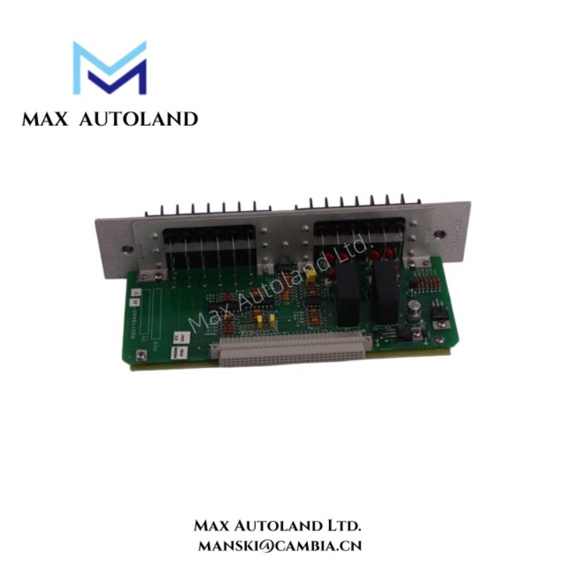
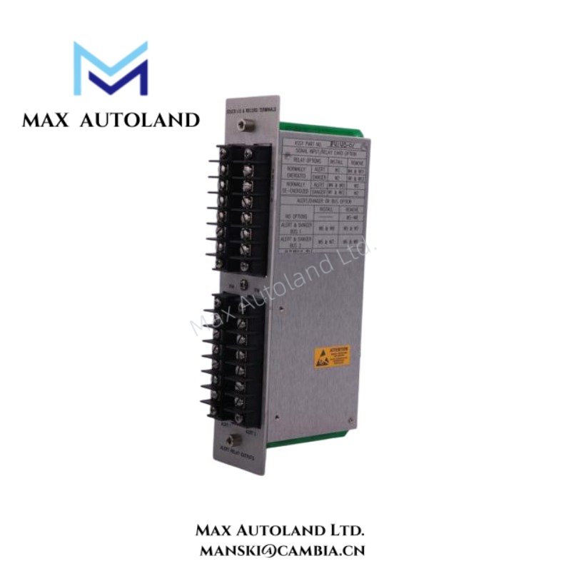
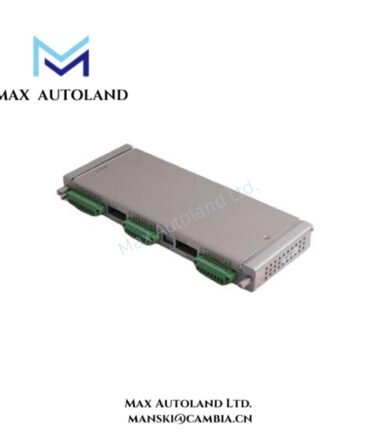
The supplied documentation identifies 84140-01 as a fixed configuration part number associated with Record Terminals Alert Relay Outputs hardware. The source material does not define an official suffix or option breakdown.
Specifications
| ParameterSpecification | |
| Model | 84140-01 |
| Brand | Bently Nevada |
| Origin | Manufacturer documentation referenced |
| Product Series | 3300 System |
| Device Type | Record Terminals Alert Relay Outputs |
| Functional Role | Alarm relay output termination and signal interface |
| System Compatibility | Bently Nevada 3300 monitoring systems |
| Signal Function | Relay output handling and terminal interconnection |
| Mounting Method | System hardware dependent |
| Weight | Not explicitly specified in provided data |
| Dimensions | Not explicitly specified in provided data |
| Operating Temp | Refer to applicable 3300 system documentation |
| Power Consumption | Depends on installed system configuration |
Rotor Dynamics Signal Handling and Output Isolation
Within Bently Nevada monitoring architectures, alert relay output hardware transfers machine condition status from vibration monitoring channels toward external annunciation or shutdown paths. Consequently, stable signal termination and controlled wiring practice support predictable relay behavior during rotor dynamic events. In multi-channel installations, technicians typically maintain conductor separation, shield continuity, and organized terminal routing to reduce electrical coupling between adjacent monitoring and alarm circuits. Furthermore, disciplined connection practices help preserve signal integrity between sensing loops and downstream relay outputs.
Frequently Asked Questions
Q: Can the 84140-01 assembly operate as a standalone relay controller?
A: No. The hardware functions as part of a compatible Bently Nevada monitoring configuration and depends on associated monitoring electronics for alarm generation and output logic.
Q: Do field wiring practices affect relay output behavior?
A: Yes. Routing output conductors near switching circuits, motor feeders, or high-current cabling can introduce unwanted electrical interference into low-level monitoring and alarm paths.
Q: Does terminal maintenance require system verification after service activity?
A: Yes. After maintenance or rewiring, technicians typically verify terminal tightness, conductor identification, relay state behavior, and continuity across associated output circuits.
Field Installation Guidelines
Install the assembly according to the designated 3300 system mounting arrangement and maintain correct terminal identification throughout field wiring activity. Route output conductors separately from power distribution cables, contactor wiring, and variable-frequency drive circuits. Apply shield grounding according to site electrical practice, and avoid uncontrolled multi-point grounding arrangements. Before returning the system to operation, inspect terminal engagement, verify conductor integrity, and confirm expected alert relay response through controlled alarm testing.





Reviews
There are no reviews yet.