


Overview
Specifications
| ParameterSpecification | |
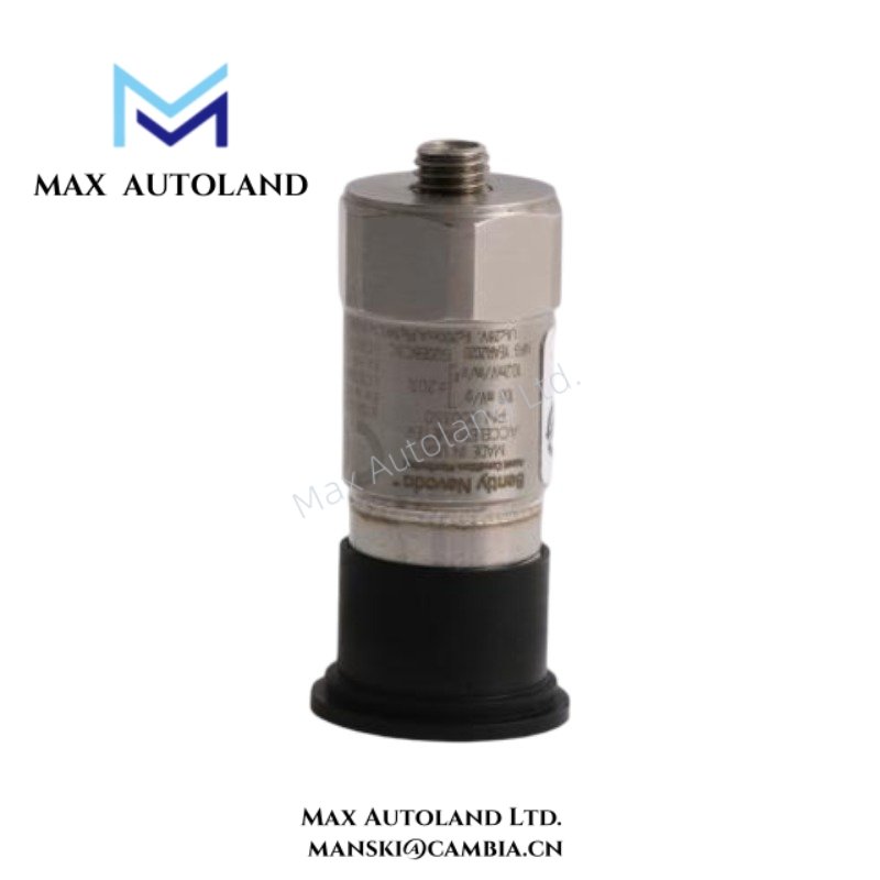
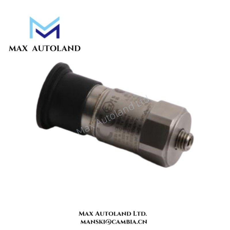
| Model | 200350-02-00 |
| Brand | Bently Nevada |
| Origin | Baker Hughes / Bently Nevada |
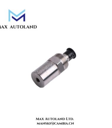
| Product Type | Accelerometers |
| Sensor Function | Vibration and acceleration measurement |
| Measurement Principle | Seismic accelerometer sensing |
| Output Type | Dynamic vibration signal |
| Installation Method | Mechanical surface mounting |
| Associated Series | Bently Nevada 200350 / 200355 |
| Dimensions | Refer to manufacturer dimensional drawing |
| Weight | Not specified in source data |
| Operating Temp | Refer to manufacturer environmental specifications |
| Power Consumption | Sensor loop dependent |
Rotor Dynamics and Eddy-Current Scaling Context
The 200350-02-00 operates in machinery condition monitoring environments where rotor dynamics evaluation depends on multiple sensing technologies. Accelerometer outputs complement eddy-current proximity probe measurements by tracking casing motion rather than shaft-relative displacement.
When deployed alongside proximity transducer systems, technicians frequently compare vibration channel behavior with probe-derived shaft data during startup and transient operating conditions.
For proximity monitoring channels within the same architecture, installation practice commonly includes gap voltage validation near -10 VDC targets. This verification confirms acceptable probe mechanical positioning before correlation with vibration measurements.
Frequently Asked Questions
Q: Does the 200350-02-00 require controlled cable routing during installation?
A: Yes. Sensor cabling should remain separated from motor feeders, switching circuits, and variable frequency drive output wiring to reduce induced noise.
Q: Can the accelerometer share grounding paths with high-current equipment conductors?
A: Grounding practices should follow instrumentation wiring rules. Shared return paths with power conductors can introduce measurement disturbance.
Q: Does sensor mounting affect vibration measurement behavior?
A: Yes. Mounting surface condition, fastener integrity, and mechanical coupling influence signal transmission between machine structure and sensing element.
Field Installation Guidelines
Prepare the mounting surface before sensor installation. Remove coating residue, contamination, or uneven surface material that can affect mechanical coupling.
Apply the specified mounting method defined by the sensor installation documentation. Verify thread engagement, seating condition, and cable strain relief after installation.
Route sensor wiring through protected cable paths. Avoid tight bending radii, unsupported cable spans, and proximity to switching equipment.
Where accelerometers operate with proximity probe channels, validate channel identification and maintain separation between low-level instrumentation wiring and power distribution conductors.





Reviews
There are no reviews yet.