


Overview
Specifications
| ParameterSpecification | |
| Model | 81545-01 |
| Brand | Bently Nevada |
| Origin | GE / Bently Nevada |
| Product Type | Signal Input Alarm Output Modules |
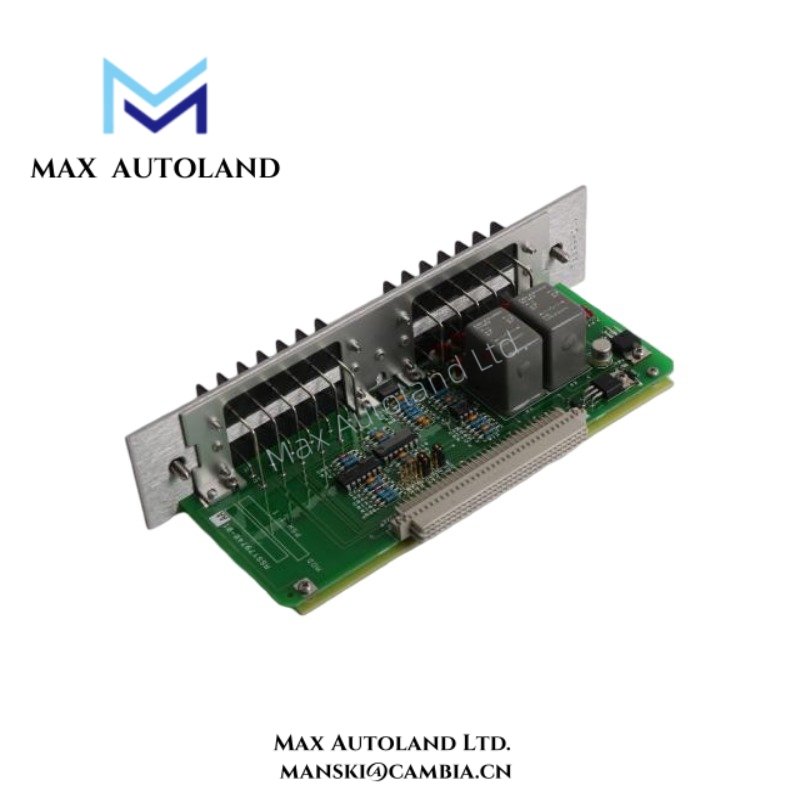
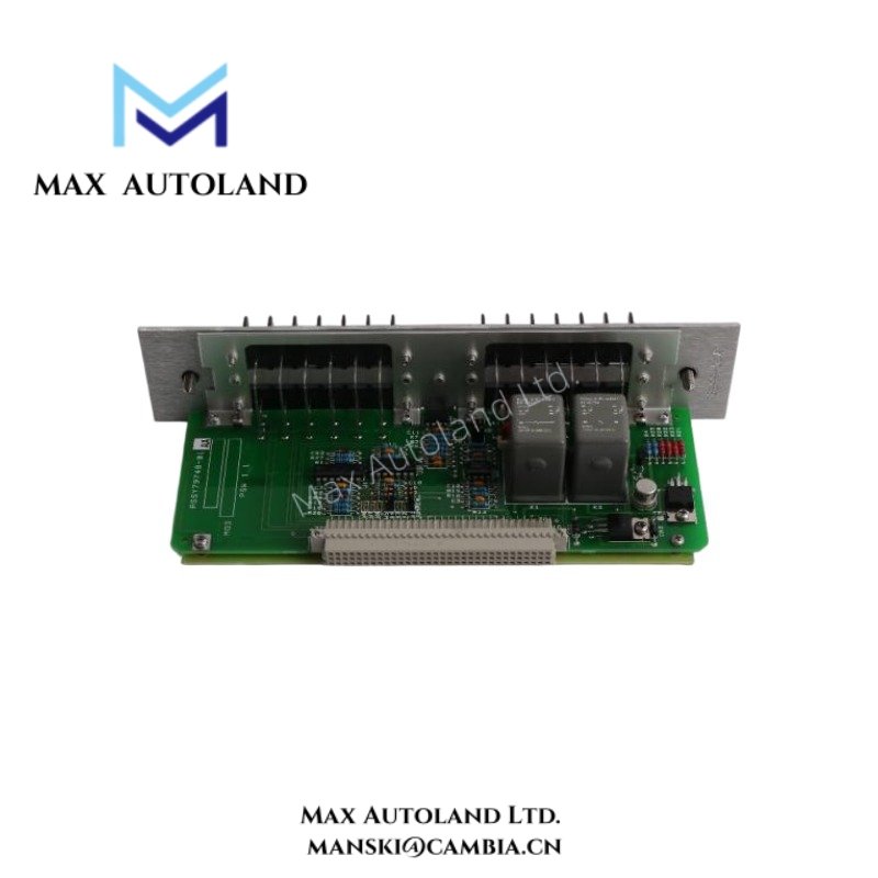
| Module Function | XDCR I/O, record terminal, and dual relay interfacing |
| Relay Configuration | Dual epoxy relay arrangement |
| Interface Type | Signal input and terminal output interface |
| Signal Handling | Monitoring signal transfer and alarm switching |
| Mounting Method | System-integrated module installation |
| Dimensions | Not specified in source data |
| Weight | Not specified in source data |
| Operating Temp | Refer to associated system environmental specifications |
| Power Consumption | Depends on installed system configuration |
Eddy-Current Probe Scaling and Cross-Talk Suppression
The 81545-01 module operates within machinery monitoring architectures where low-level transducer signals and relay switching circuits coexist. Signal path behavior depends on controlled isolation between measurement channels and alarm actuation circuits.
Cross-talk suppression practices include shield continuity, segregated cable routing, and separation between transducer conductors and relay-driven wiring. These methods reduce switching noise transfer into measurement paths.
In proximity monitoring environments, eddy-current probe scaling remains dependent on calibrated probe chain response. Installation validation commonly includes nominal gap voltage verification near -10 VDC targets where applicable to the monitored channel design.
Frequently Asked Questions
Q: Does the 81545-01 support direct relay alarm switching functions?
A: The module incorporates a dual epoxy relay arrangement associated with signal handling and alarm-related output execution within the monitoring assembly.
Q: Are XDCR signal cables required to remain isolated from relay conductors?
A: Yes. Low-level transducer wiring should remain physically separated from relay output paths to reduce induced noise and coupling effects.
Q: Can the module be installed without grounding attention to shield terminations?
A: No. Shield grounding practices should follow the associated monitoring system installation rules to control noise ingress and loop current behavior.
Field Installation Guidelines
Confirm terminal identification before landing field conductors. Maintain consistent wire labeling between XDCR inputs, record terminals, and relay output points.
Route transducer cables separately from contactor wiring, AC feeders, and relay switching conductors. Use shielded instrumentation cable where defined by the monitoring architecture.
Inspect terminal clamping integrity before system energization. Loose conductors can introduce intermittent signal behavior or unintended relay operation.
Where relay outputs interface with external annunciation or shutdown circuits, verify continuity and polarity against the applicable system wiring diagram.


Reviews
There are no reviews yet.