

Overview
Suffix Breakdown & Model Matrix
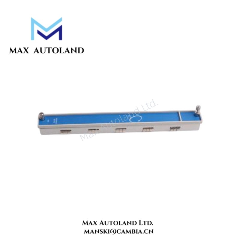
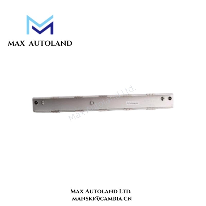
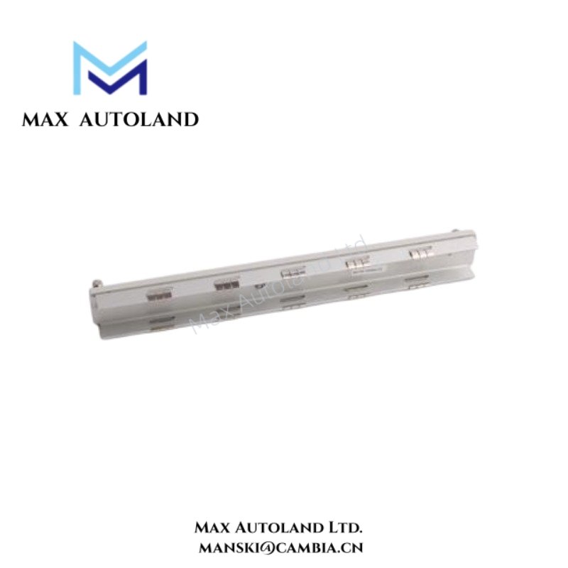
The supplied documentation identifies 24765-01-01 as a fixed ordering configuration within the Bently Nevada thermal expansion sensing family. No official suffix decomposition is defined in the referenced material.
Specifications
| ParameterSpecification | |
| Model | 24765-01-01 |
| Brand | Bently Nevada |
| Origin | United States |
| Product Type | Thermal Expansion Sensors |
| Measurement Function | Case / thermal expansion displacement monitoring |
| Signal Principle | Mechanical displacement sensing |
| System Compatibility | Bently Nevada machinery monitoring systems |
| Mounting Application | Turbine and rotating equipment casing expansion points |
| Weight | Not explicitly specified in supplied source |
| Dimensions | Not explicitly specified in supplied source |
| Operating Temp | Refer to manufacturer environmental specification |
| Power Consumption | Passive sensor element; system-side conditioning dependent |
Gap Voltage Validation and Rotor Dynamics Correlation
Within Bently Nevada TSI measurement environments, thermal expansion values are evaluated together with shaft position, vibration, and rotor dynamic variables. Expansion sensor interpretation frequently forms part of machine warm-up and transient operating assessment.
Where proximity transducer systems operate in parallel with expansion channels, commissioning procedures commonly validate eddy-current probe bias behavior near nominal -10 VDC target conditions. Stable gap voltage behavior supports correlation between rotor movement and casing thermal growth trends while reducing ambiguity during startup thermal transients.
Frequently Asked Questions
Q: Does the 24765-01-01 support hot-swap replacement during live monitoring operation?
A: Replacement practice depends on the host monitoring rack and channel configuration. Standard field procedure isolates the associated measurement channel before mechanical removal or reconnection.
Q: Is shield grounding required for thermal expansion sensor wiring?
A: Yes. Cable shielding should follow the monitoring system grounding scheme. Single-point shield termination is typically applied to reduce induced noise loops and measurement instability.
Q: Can the sensor output be interpreted independently from vibration channels?
A: The sensor can operate as an independent displacement input, but engineering evaluation commonly compares expansion trends with vibration, axial position, and startup thermal profiles.
Field Installation Guidelines
Install the sensor assembly using rigid mechanical attachment hardware to prevent measurement error caused by bracket flexure or thermal distortion of mounting structures.
Maintain separation between sensor wiring and high-energy motor, relay, or switching conductors. Avoid parallel routing with power cabling where possible.
Verify alignment across the intended expansion travel path before final tightening. Mechanical preload, side loading, or angular misalignment can introduce displacement offset and non-repeatable response.
Apply plant grounding practice consistently. Shield continuity, enclosure bonding, and clean termination surfaces should be confirmed during commissioning.



Reviews
There are no reviews yet.