

Overview
Suffix Breakdown & Model Matrix
The supplied documentation identifies 105375-01 as a fixed catalog number. No official suffix matrix or ordering code breakdown is provided for this model; therefore, no suffix interpretation is included.
Hardware Specifications
| Parameter | Specification |
|---|---|
| Model | 105375-01 |
| Brand | Bently Nevada |
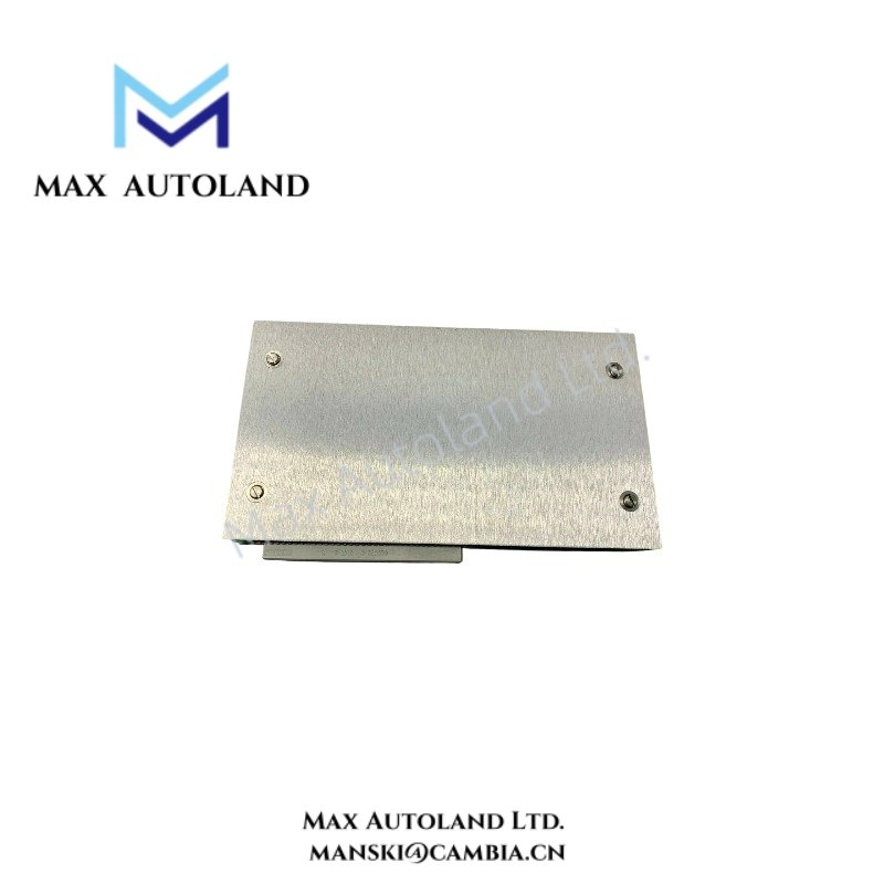
| Product Type | LED Indicator Board / Sampler Status Module |
| Series | 2150/2155 |
| Manufacturer | Miscellaneous Manufacturers |
| Origin | Not specified |
| Weight | 0.3 kg |
| Dimensions | 2.5 cm × 19.1 cm × 10.2 cm |
| Operating Temp | Not specified |
| Power Consumption | Not specified |
| Primary Function | Visual indication of sampler operating and status conditions |
| Installation | System backplane or designated equipment slot |
| Status Indication | Multiple LED status indicators |
| Compatible System | Bently Nevada Series 2150/2155 |
Eddy-Current Monitoring Interface Considerations
Although the 105375-01 is an LED indication board rather than a vibration measurement module, it operates within a machinery protection platform where eddy-current probe measurements are processed by associated electronics. During commissioning of the complete system, probe gap voltage should be verified against the specified target values before interpreting front-panel status indications. Proper grounding, shield termination, and signal separation help minimize cross-talk between adjacent monitoring channels and maintain consistent status reporting throughout the rack.
Frequently Asked Questions
Q: Does the 105375-01 support hot replacement while the rack remains energized?
A: Hot replacement capability is not specified in the available documentation. Follow the maintenance procedure defined for the host Series 2150/2155 system before removing or installing the board.
Q: Does the LED Indicator Board perform vibration signal processing?
A: No. The board functions as a hardware status indication interface. Measurement acquisition and signal processing are performed by associated monitoring modules.
Q: Does the module require field calibration?
A: No calibration information is provided for the LED indicator board itself. Verification normally consists of confirming correct LED operation after installation and validating system status through the associated monitoring modules.
Field Installation Guidelines
- Disconnect or isolate system power according to plant maintenance procedures before inserting or removing the board unless the host system documentation explicitly permits energized replacement.
- Verify the board orientation and connector alignment before installation to prevent backplane connector damage.
- Ensure mounting hardware is securely fastened to minimize vibration transmitted to the circuit assembly.
- Route signal and power wiring separately where applicable to reduce electrical interference.
- Maintain proper protective earth and cable shield termination in accordance with the installation manual for the complete monitoring system.
- After installation, confirm that all LED indicators correspond to the expected operating state reported by the associated sampler status module.



Reviews
There are no reviews yet.