

Overview
Hardware Specifications
| Parameter | Specification |
|---|---|
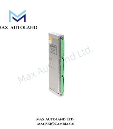
| Model | Bently Nevada 3500/53 |
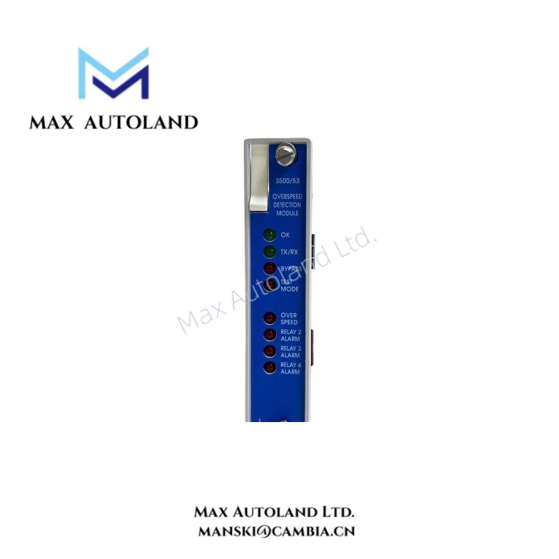
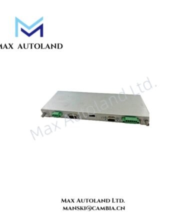
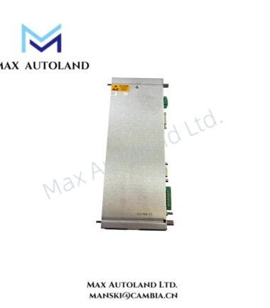
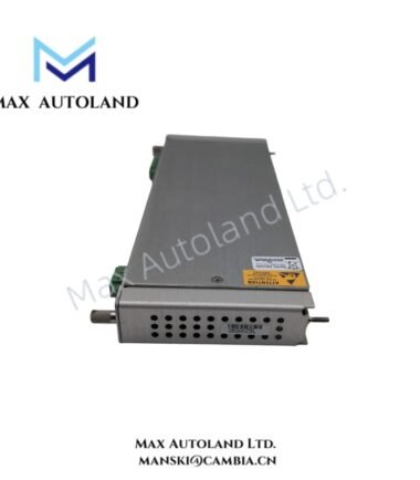
| Product Type | Electronic Overspeed Detection System / Module |
| Brand | Bently Nevada |
| Origin | Not specified in supplied data |
| System Platform | Bently Nevada 3500 Machinery Monitoring System |
| Protection Function | Electronic overspeed detection |
| Voting Architecture | 2-out-of-2 or 2-out-of-3 |
| Recommended Voting | 2-out-of-3 |
| Input Signal Types | Proximity probe transducers; passive or active magnetic pickups |
| Input Signal Range | +10.0 V to -24.0 V, internally limited |
| Input Impedance | 20 kOhm |
| Maximum Input Frequency | 20 kHz |
| Events per Revolution | 1 to 255 |
| Full-Scale Speed Range | Up to 99,999 rpm |
| Recorder Output | +4 to +20 mA, proportional to module full-scale range |
| Transducer Power Supply | -24 VDC, 40 mA maximum |
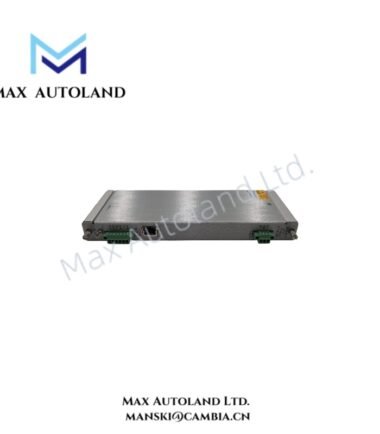
| Buffered Transducer Output | Front-panel coaxial connector |
| Buffered Output Impedance | 550 Ohm |
| RPM Accuracy Below 100 rpm | +/- 0.1 rpm |
| RPM Accuracy, 100 to 10,000 rpm | +/- 1 rpm |
| RPM Accuracy, 10,000 to 99,999 rpm | +/- 0.01% |
| Monitor Module Power Consumption | 8.0 W typical |
| Operating Temperature | -30 deg C to +65 deg C |
| Storage Temperature | -40 deg C to +85 deg C |
| Humidity | Up to 95%, non-condensing |
| Monitor Module Dimensions | 241.3 mm x 24.4 mm x 241.8 mm |
| Monitor Module Weight | 0.82 kg |
| I/O Module Dimensions | 241.3 mm x 24.4 mm x 99.1 mm |
| I/O Module Weight | 0.45 kg |
| Rack Requirement | 3500 rack with redundant power supplies |
| Applicable Standards | API 670 and API 612 |
Overspeed Detection and Rotor Dynamics
The 3500/53 processes speed pulses from redundant tachometer inputs and evaluates the measured rotational speed against configured protection limits. Therefore, the module can initiate overspeed protection according to the selected voting architecture.
The input stage accepts proximity probes and passive or active magnetic pickups. In addition, the 20 kHz maximum input frequency allows the system to process high-speed pulse signals without requiring an external frequency converter.
For proximity probe installations, technicians should validate the probe gap voltage before commissioning. A typical Bently Nevada eddy-current probe installation uses a negative gap voltage target, commonly around -10 VDC, when the applicable probe system specifies this operating point.
The redundant speed channels support voting logic that separates valid overspeed conditions from an isolated channel fault. A 2-out-of-3 arrangement provides three independent speed inputs and requires two channels to assert the corresponding protection condition.
The front-panel buffered outputs provide access to raw transducer signals through coaxial connectors. Consequently, technicians can observe the sensor waveform without modifying the primary speed-processing circuit.
Frequently Asked Questions
Q: What transducers can the 3500/53 accept?
A: The module accepts proximity probe transducers and passive or active magnetic pickups within the specified input electrical range.
Q: What voting configurations does the 3500/53 support?
A: The supplied data specifies 2-out-of-2 and 2-out-of-3 voting configurations, with 2-out-of-3 identified as the recommended configuration.
Q: Does the 3500/53 require redundant rack power?
A: Yes. The supplied specifications require installation in a 3500 rack equipped with redundant power supplies.
Field Installation Guidelines
- Install the monitor in a compatible Bently Nevada 3500 rack and provide the specified redundant power arrangement.
- Route speed-sensor wiring separately from high-voltage power conductors and high-current switching circuits.
- Maintain proper cable shielding and grounding practices to reduce electromagnetic interference on low-level speed signals.
- Verify each proximity probe installation mechanically before applying power.
- For eddy-current probes, verify the probe gap and corresponding DC bias voltage against the applicable transducer system specification.
- Check the polarity and termination of magnetic pickup wiring before commissioning.
- Confirm that each tachometer channel produces a stable pulse waveform across the intended operating speed range.
- Verify the configured voting logic before placing the overspeed protection function into service.
- Use the front-panel buffered outputs for diagnostic waveform observation where required.
- Do not alter field wiring or protection logic while the overspeed protection circuit remains in an active shutdown state.
Reviews
There are no reviews yet.