
Overview
Hardware Specifications
| Parameter | Specification |
|---|---|
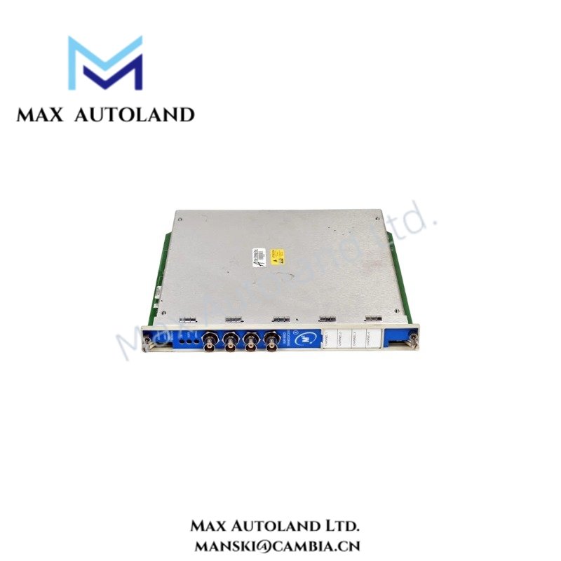
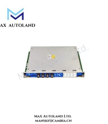
| Model | 3500/44M 176449-03 |
| Base Model | 3500/44M |
| Brand | Bently Nevada |
| Product Type | Aeroderivative GT Vibration Monitor |
| Spare Model | 176449-03 |
| Origin | USA |
| Weight | 0.8 kg |
| Dimensions | Estimated shipping size: 2.6 x 25.8 x 24 cm |
| Operating Temp | -30 deg C to +65 deg C |
| Humidity | 95%, non-condensing |
| Power Consumption | Not specified in provided data |
| Transducer Power Supply | 23 VDC nominal, 43 mA maximum |
| Output Impedance | 550 ohm |
| Direct Signal Bandwidth | 4 Hz to 30 kHz, -3 dB |
| Low-Pass Corner | 200 Hz, -3 dB |
| High-Pass Corner | 25 Hz, 75 Hz, or 100 Hz, -3 dB |
Aeroderivative Vibration Signal Characteristics
The 3500/44M accepts vibration-related transducer signals and applies defined frequency-response characteristics before signal output. The direct signal path supports 4 Hz to 30 kHz at the -3 dB points. In addition, the low-pass filter uses a 200 Hz corner frequency, while the high-pass filter provides selectable 25 Hz, 75 Hz, or 100 Hz corner frequencies.
The transducer supply provides 23 VDC nominal voltage with a maximum current of 43 mA. Therefore, field wiring must maintain the required supply and signal integrity at the connected transducer.
For Bently Nevada vibration measurement systems, technicians should also verify probe gap voltage and signal scaling during commissioning. Eddy-current probe systems commonly use approximately -10 VDC as a nominal gap-voltage target, but the actual target must follow the applicable probe and monitor documentation.
The 550 ohm output impedance should also be considered when engineers connect downstream monitoring or signal-conditioning equipment. Furthermore, technicians should route vibration signal wiring separately from high-current switching conductors to reduce electrical interference and cross-talk.
Frequently Asked Questions
Q: What transducer supply does the 3500/44M 176449-03 provide?
A: The supplied data specifies 23 VDC nominal with a maximum transducer current of 43 mA.
Q: What frequency range does the direct signal path support?
A: The direct signal path is specified from 4 Hz to 30 kHz at -3 dB.
Q: Does the provided data specify the module power consumption?
A: No. The supplied specifications define transducer power, but they do not state the module’s total power consumption.
Field Installation Guidelines
- Install the module in the designated 3500 rack position and follow the rack installation documentation for mechanical retention.
- Confirm connector orientation and module seating before applying rack power.
- Route vibration signal cables separately from AC power, contactor wiring, and high-current switching circuits.
- Maintain appropriate cable shielding practices for the connected vibration transducer circuit. Ground the shield according to the applicable Bently Nevada installation documentation and site grounding scheme.
- Verify transducer supply voltage and current requirements before connecting field devices.
- During commissioning, verify vibration signal polarity, scaling, filter configuration, and probe gap voltage against the applicable transducer and monitor documentation.
- Do not treat the estimated shipping dimensions as the installed module envelope. Use the manufacturer mechanical drawing when enclosure clearance or rack spacing requires exact dimensions.
- Operate the module within the specified ambient range of -30 deg C to +65 deg C and maintain non-condensing humidity conditions.
Reviews
There are no reviews yet.