


Overview
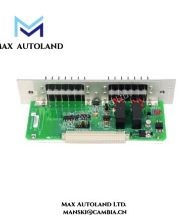
Hardware Specifications
| Parameter | Specification |
|---|---|
| Model | Bently Nevada 126623-01 |
| Origin | USA |
| Weight | 0.26 kg |
| Dimensions | 5 x 9.8 x 22.8 cm |
| OperatingTemp | -40 degC to +85 degC |
| PowerConsumption | <15 W (typical) |
| Supply Voltage | 24 VDC +/-10 percent |
| Input Channels | 2 independent channels |
| Input Signal Range | +/-10 V (IEPE), 4-20 mA (Velocity) |
| Sampling Rate | Up to 100 kHz per channel |
| Frequency Response | 0.5 Hz to 20 kHz (+/-3 dB) |
| Dynamic Range | 100 dB typical |
| ADC Resolution | 24-bit |
| Analog Output | 4-20 mA |
Eddy Current Probe Scaling and Gap Voltage Validation Behavior
The module interfaces with eddy-current proximity measurement chains and supports scaling consistency across vibration channels through linearized signal conditioning. Gap voltage validation logic operates against negative DC bias reference levels (nominal -10 VDC target domain), ensuring stable displacement translation from probe front-end to processing backplane. Signal integrity is maintained under rotor dynamic excitation conditions where phase drift and amplitude aliasing may occur. Cross-talk suppression is implemented at channel separation level to minimize coupling between adjacent measurement paths during high frequency vibration events.
Suffix Breakdown and Model Matrix
126623-01 is a single defined ordering identifier. No factory-published suffix segmentation or functional sub-revision matrix is specified for decomposition. Electrical and mechanical characteristics are defined at assembly level only.
Frequently Asked Questions
Q: Can the module operate in hot-swap conditions within the rack system?
A: The module supports rack insertion within energized backplane environments, but signal channels require stabilization time after insertion due to internal ADC synchronization and channel initialization sequencing.
Q: What is the backplane power loading behavior?
A: Backplane consumption is derived from the 24 VDC supply input and remains under 15 W typical, with transient variation during sampling burst initiation at maximum channel rate.
Q: Is firmware-level signal scaling configurable externally?
A: Signal scaling is handled through system-level configuration; the module itself does not expose standalone firmware scaling adjustments at hardware level.
Field Installation Guidelines
Maintain correct backplane alignment prior to insertion to prevent connector pin stress. Shielded cabling must be terminated with single-point grounding to avoid circulating current loops in vibration signal return paths. IEPE input lines should remain isolated from high-current switching conductors to reduce induced noise coupling. Ensure module seating is fully engaged across the rack connector interface before energization. Do not apply mechanical force to front-panel interface during installation or removal.



Reviews
There are no reviews yet.