
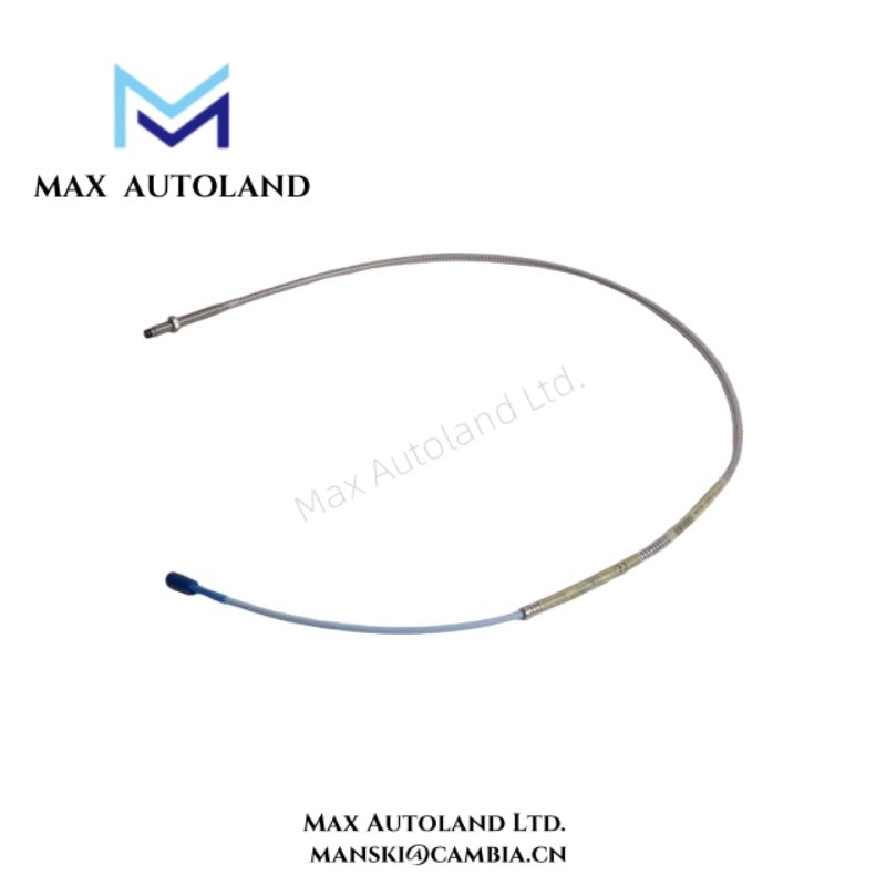
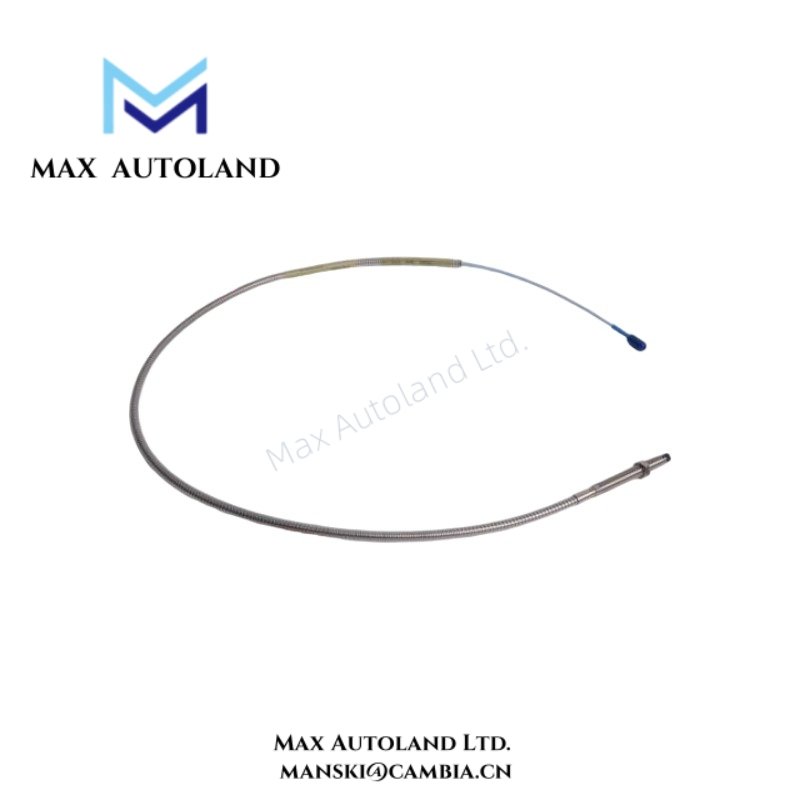
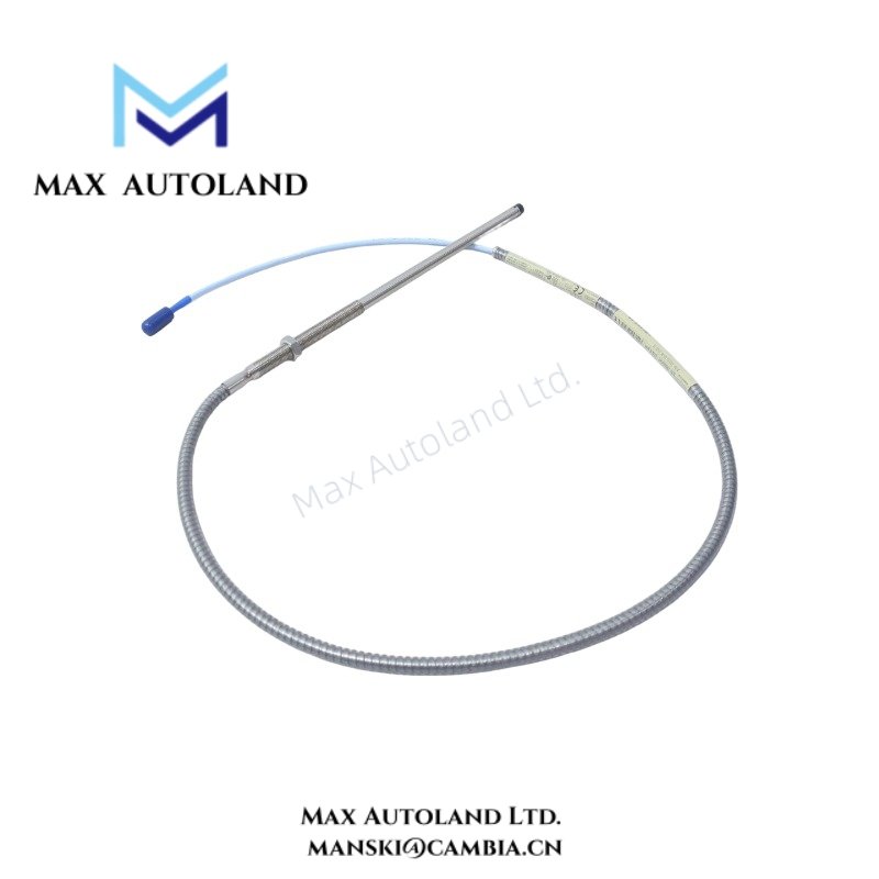
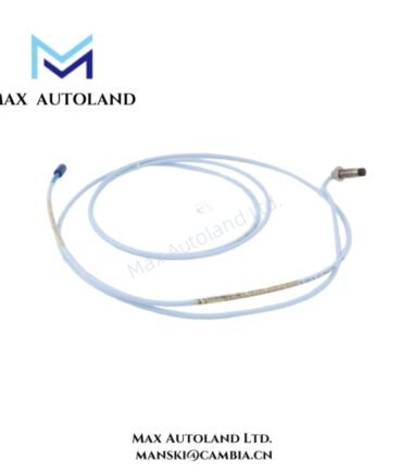
Overview
Specifications
| ParameterSpecification | |
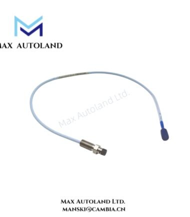
| Model | 330102-00-28-10-02-05 |
| Brand | Bently Nevada |
| Series | 3300 XL 8 mm |
| Product Type | Proximity Transducers |
| Origin | USA |
| Probe Type | Non-contact eddy-current proximity probe |
| Probe Diameter | 8 mm |
| Measurement Function | Radial vibration, shaft position, and displacement monitoring |
| System Compatibility | Bently Nevada 3300 XL proximity transducer systems |
| Target Material | Electrically conductive metallic targets |
| Signal Chain Requirement | Probe, extension cable, and compatible Proximitor/driver electronics |
| Output Characteristic | Electrical response proportional to target displacement |
| Mounting Method | Threaded mechanical installation |
| Cable Interface | Integrated probe lead for matched system configuration |
| Weight | Not explicitly specified by supplied source |
| Dimensions | Configuration-dependent; refer to manufacturer mechanical data |
| Operating Temp | Refer to official Bently Nevada environmental specification |
| Power Consumption | Defined by associated signal conditioning electronics, not by probe element alone |
Rotor Dynamics and Cross-Talk Suppression
Within multi-channel TSI measurement arrangements, probe positioning and cable routing directly affect rotor dynamic signal quality. Closely grouped radial probes can experience unwanted electromagnetic interaction if cable separation and shielding practices are not maintained.
The 3300 XL 8 mm transducer architecture is intended for calibrated operation as a matched probe system. Cross-talk suppression depends on controlled installation geometry, grounded shielding practices, and separation from variable-frequency drive power conductors or high-current switching paths.
During startup verification, measured waveform behavior should be reviewed against expected rotor response characteristics, including synchronous vibration content, mechanical runout influence, and probe bias stability.
Frequently Asked Questions
Q: Can this proximity transducer be operated with unmatched extension cables?
A: The sensing chain is designed for matched system components. Cable substitution or electrical length changes can alter system scaling and calibration behavior.
Q: Is field trimming of the probe cable permitted during installation?
A: Field shortening, splicing, or conductor modification should not be performed unless explicitly defined by manufacturer procedures, because impedance changes affect measurement response.
Q: Does replacement require system power removal?
A: Replacement practice depends on the connected monitoring hardware and site procedures. Mechanical access near rotating equipment generally requires isolation, safe shutdown status, and post-installation signal validation.
Field Installation Guidelines
Install the probe assembly with rigid mechanical support and controlled probe-to-target alignment. Verify unobstructed target surface exposure before final tightening.
Route probe cables independently from motor feeders, contactor wiring, and switching power conductors. Maintain shielding continuity according to the plant grounding method and avoid multi-point shield termination unless specified by the installation standard.
After installation, confirm transducer response through gap voltage verification. For Bently Nevada proximity systems, commissioning commonly includes validation against expected negative DC bias behavior, including nominal operating regions near -10 VDC target conditions.







Reviews
There are no reviews yet.