

Overview
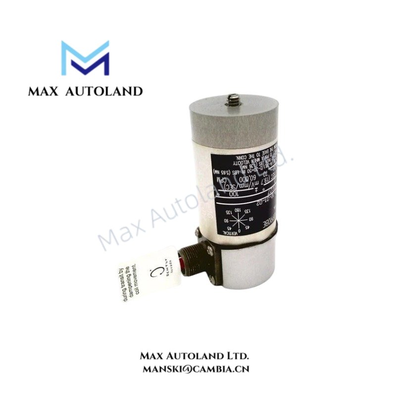
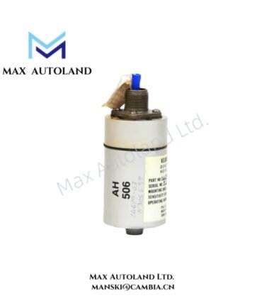
Configured for absolute casing and bearing housing vibration measurement, the Bently Nevada 16699-03-02-02 (16699 Velocity Seismoprobe) converts mechanical vibration velocity into a proportional electrical output for machinery monitoring systems. Its moving-coil sensing element provides a velocity-domain signal for continuous vibration measurement.
Hardware Specifications
| Parameter | Specification |
|---|---|
| Model | 16699-03-02-02 |
| Brand | Bently Nevada |
| Product Type | Velocity Seismoprobe / Vibration Transducer |
| Origin | Not specified |
| Weight | Approximately 0.32 kg |
| Sensor Principle | Moving-coil vibration transducer |
| Sensitivity | 500 mV/in/sec (19.7 mV/mm/sec) |
| Frequency Response | Typically 10 Hz to 1,000 Hz |
| Minimum Operating Frequency Range | 270 to 900 RPM, application dependent |
| Output Signal | Electrical signal proportional to vibration velocity |
| Mounting Options | Circular or flanged mounting bases |
| Cable Entry Options | Top, side, or terminal block entry, depending on mounting configuration |
| Primary Measurement | Absolute casing and bearing housing vibration |
Rotor Dynamics and Vibration Signal Characteristics
The 16699-03-02-02 measures casing or bearing housing motion directly as vibration velocity. The moving-coil mechanism converts mechanical movement into an electrical signal proportional to velocity.
This output provides a velocity-domain measurement for machinery vibration analysis. Therefore, monitoring equipment can use the signal to evaluate casing vibration associated with conditions such as imbalance, misalignment, and mechanical looseness.
The stated sensitivity is 500 mV/in/sec, equivalent to 19.7 mV/mm/sec. The specified frequency response extends from approximately 10 Hz to 1,000 Hz, while the minimum operating frequency range depends on the application and rotational speed.
Frequently Asked Questions
Q: What physical quantity does the 16699-03-02-02 measure?
A: It measures absolute casing and bearing housing vibration as a velocity signal.
Q: What is the electrical sensitivity of the transducer?
A: The stated sensitivity is 500 mV/in/sec, equivalent to 19.7 mV/mm/sec.
Q: Does the 16699-03-02-02 require a specific mounting arrangement?
A: The available configurations include circular or flanged mounting bases, with top, side, or terminal block entry options depending on the selected mounting arrangement.
Field Installation Guidelines
- Mount the Seismoprobe on a suitable rigid surface of the machine casing or bearing housing.
- Keep the mounting surface clean and mechanically stable before installation.
- Select the specified circular or flanged mounting arrangement for the installation configuration.
- Route the sensor cable away from high-current power conductors where practical to reduce electrical interference.
- Maintain secure mechanical fastening to prevent mounting movement from affecting the vibration measurement.
- Connect the signal wiring according to the monitoring system input requirements and the applicable installation documentation.
- Verify cable shielding and grounding practices against the machinery monitoring system wiring specification.
- Confirm the sensor orientation and mechanical mounting position before commissioning.
- Check the measured vibration signal at the monitoring system after installation and compare it with the expected velocity measurement range.
- Do not introduce unsupported temperature, power, mounting torque, or dimensional values when the applicable installation documentation does not specify them.




Reviews
There are no reviews yet.