Overview
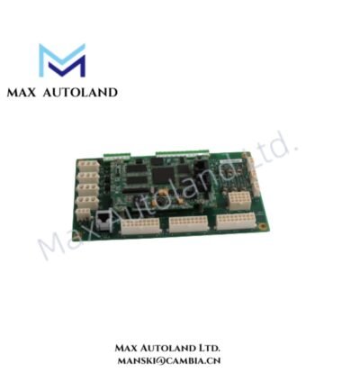
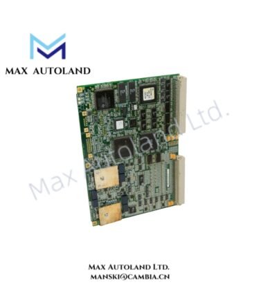
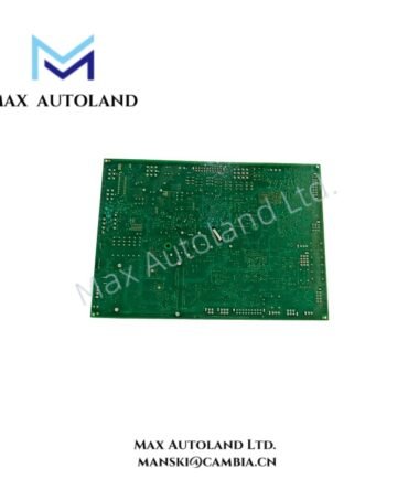
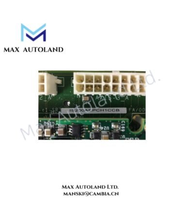
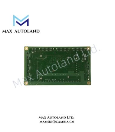
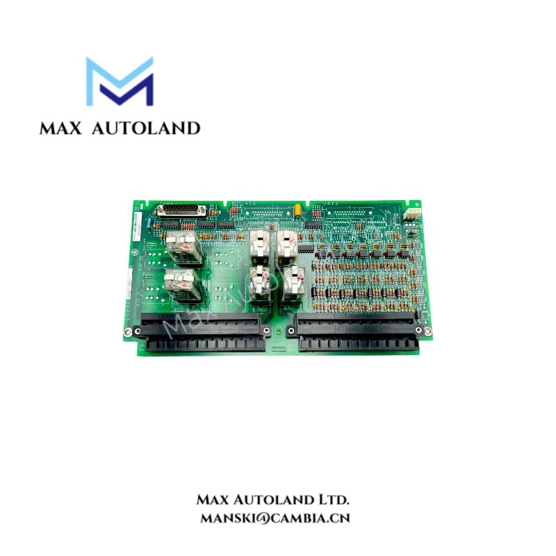
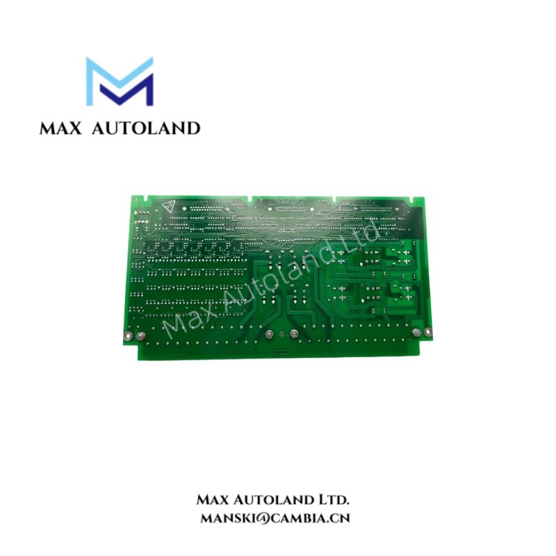
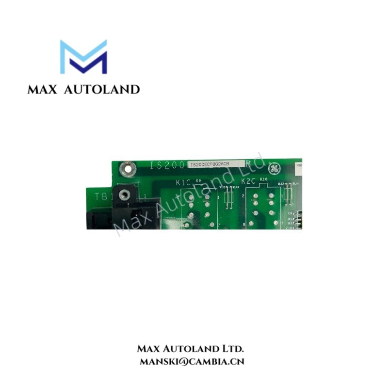
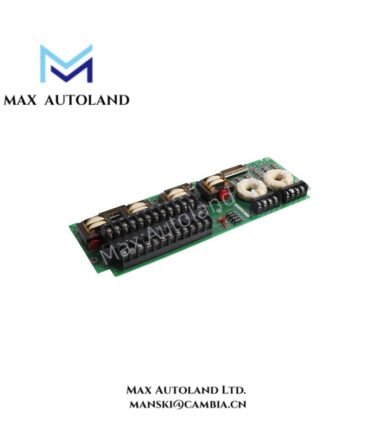
Configured for managing exciter-related contact termination and relay control signals within turbine excitation networks, the GE IS200ECTBG2A (IS200ECTBG2A Exciter Contact Terminal Board) actively provides direct physical and electrical execution.
Hardware Specifications
| Parameter | Specification |
|---|---|
| Model | IS200ECTBG2A |
| Brand | GE |
| Series | Mark VI / Mark VIe |
| Origin | United States (Standard Factory Origin) |
| Weight | Approx. 0.34 kg |
| Dimensions | Approx. 150 mm x 76 mm x 90 mm |
| Operating Temp | -20 deg C to +65 deg C (Standard industrial enclosure rating) |
| Power Consumption | Passive terminal board (Powered via customer and wetting power supplies) |
| Customer Power | 125 V DC |
| Relay Control Voltage | 24 V DC |
| Wetting Voltage | 70 V DC |
Profinet and Deterministic Network Integration
Operating within the Mark VIe control architecture, the terminal board coordinates closely with distributed I/O processors through deterministic communication paths. Firmware flash compatibility ensures that terminal configurations align with system-level software revisions. Furthermore, engineers maintain backplane bus communication velocity and I/O density scaling to prevent data bottlenecks across turbine control enclosures. Consequently, firmware flash compatibility successfully verifies that terminal status reports transmit without packet delay or corruption.
Frequently Asked Questions
Q: What are the specific power supply ratings connected to this terminal board?
A: The board manages a customer power input of 125 V DC, a relay control voltage of 24 V DC, and a wetting voltage of 70 V DC for specific contact states.
Q: Is the IS200ECTBG2A hot-swappable during active turbine operation?
A: No. Because live excitation and control voltages are present, operators must completely isolate system power before installing or removing the terminal board to prevent electrical arc faults or hardware damage.
Q: How do technicians execute physical mounting for this module?
A: Technicians mount the unit onto a standard panel or DIN-rail configuration depending on the specific cabinet assembly layout within the turbine enclosure.
Field Installation Guidelines
- Isolation Verification: First, verify that all associated customer power feeds (125 V DC), relay control lines (24 V DC), and wetting circuits (70 V DC) are completely de-energized and locked out prior to physical handling.
- DIN-Rail or Panel Securing: Next, align the module onto the designated DIN-rail or mounting panel inside the turbine control cabinet. Secure all mounting screws or clips firmly so the hardware withstands vibration.
- Wiring Terminations: Then, connect incoming signal and power cables to the designated terminal blocks, ensuring secure mechanical torque to prevent loose connections under thermal expansion.
- Shielding and Grounding: Terminate cable shields directly to the cabinet grounding bar to suppress electromagnetic interference and ensure stable signal transmission.
- Post-Installation Inspection: Finally, perform a multimeter continuity and voltage isolation check across all connected terminals before you restore system power.