
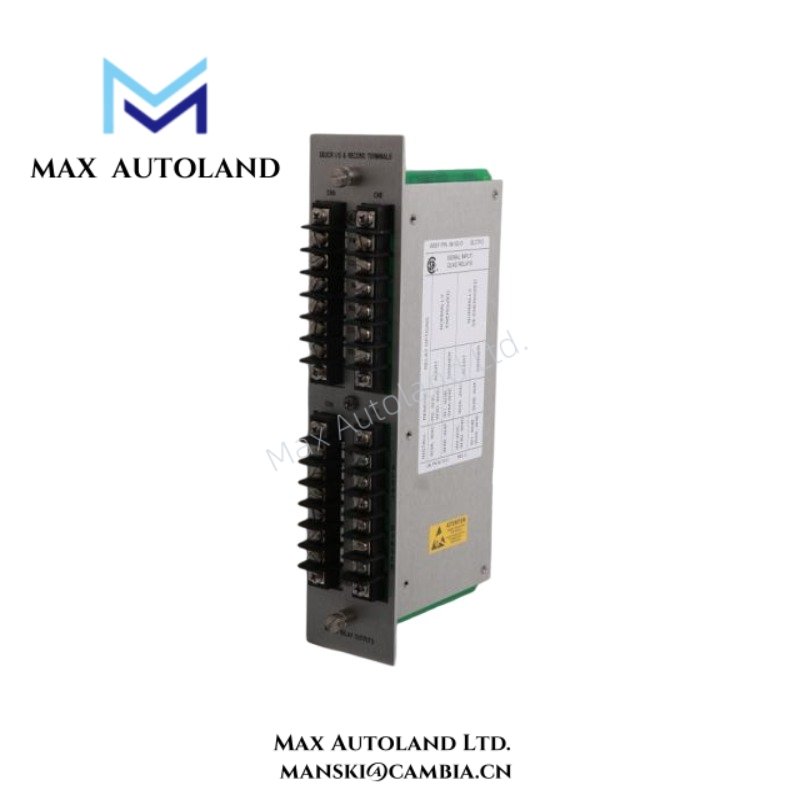

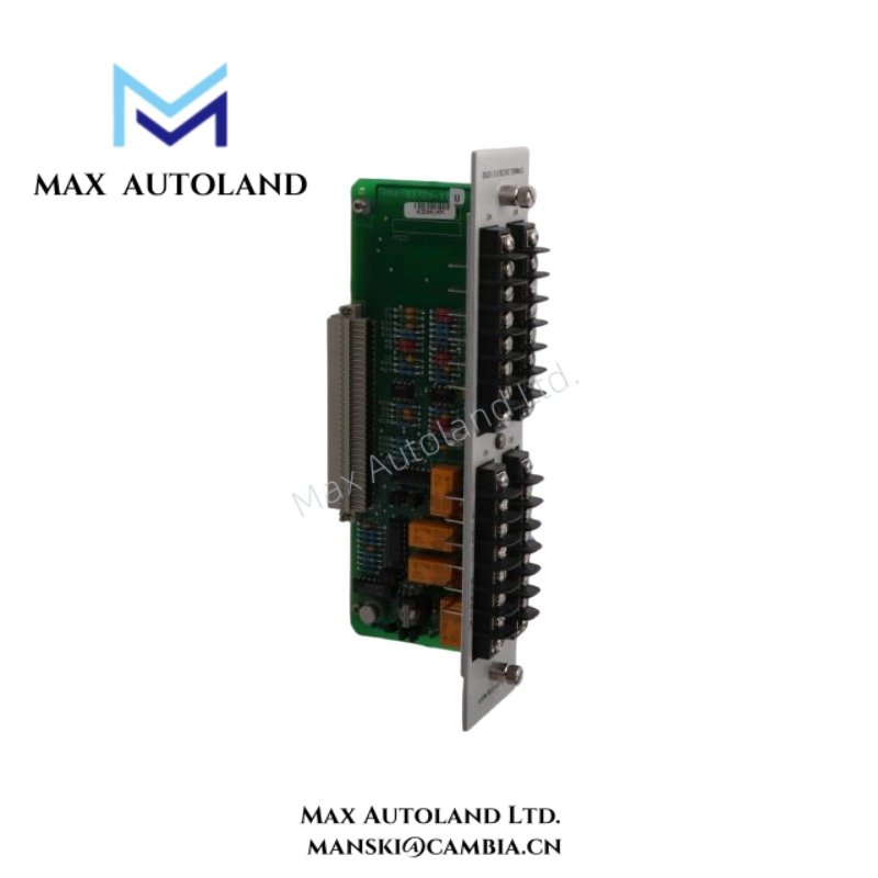


Overview
Specifications
| ParameterSpecification | |
| Model | 83729-01 |
| Brand | Bently Nevada |
| Product Type | Terminal Assemblies |
| Function | Xducer I/O and record signal termination |
| Application | Signal routing and field interconnection |
| System Association | Bently Nevada 3300 System |
| Origin | Not explicitly specified |
| Weight | Not explicitly specified |
| Dimensions | Not explicitly specified |
| Operating Temp | Not explicitly specified |
| Power Consumption | Passive assembly; consumption data not specified |
| Signal Interface | Transducer I/O and record terminal connections |
| Mounting Method | System panel / internal assembly mounting |
Eddy-Current Probe Scaling and Signal Path Behavior
Within Bently Nevada mechanical monitoring configurations, terminal assemblies influence signal quality between eddy-current transducers, monitoring modules, and record output circuits. Therefore, technicians typically verify conductor continuity, shield termination integrity, and terminal retention before commissioning.
In addition, eddy-current probe scaling depends on stable electrical transfer across the complete signal path. When installers validate gap voltage conditions near expected setup targets, often around -10 VDC during alignment procedures, they can confirm probe positioning, conductive coupling, and measurement readiness. Poor terminal contact, however, can increase noise susceptibility, disturb scaling consistency, and alter recorded vibration behavior.
Frequently Asked Questions
Q: Does the 83729-01 provide active signal conversion or amplification?
A: No. The available documentation identifies the unit as a terminal and I/O assembly. Accordingly, the hardware supports signal termination and routing functions rather than active conditioning or amplification.
Q: Can technicians replace the 83729-01 while the associated monitoring system remains energized?
A: The referenced material does not define a hot-swap operating condition. Therefore, technicians should isolate system power, verify safe electrical conditions, and then perform removal or installation activities.
Q: Which wiring practices support stable transducer signal transmission through the assembly?
A: Installers should separate low-level transducer wiring from high-current conductors, maintain shield continuity according to the selected grounding scheme, and avoid extended parallel routing near switching devices or drive power cables.
Field Installation Guidelines
Before installation, technicians should verify connector orientation, terminal identification, and assembly compatibility with the target Bently Nevada 3300 System hardware.
Next, installers should route transducer cables away from electromagnetic noise sources, including motor feeders, switching supplies, and variable frequency drive conductors. They should also maintain consistent shield grounding practices throughout the signal loop.
Finally, personnel should inspect terminal tightness and connector engagement after installation. Loose connections can create intermittent record outputs, unstable transducer signals, or elevated contact resistance within the monitoring circuit.





Reviews
There are no reviews yet.