
Overview
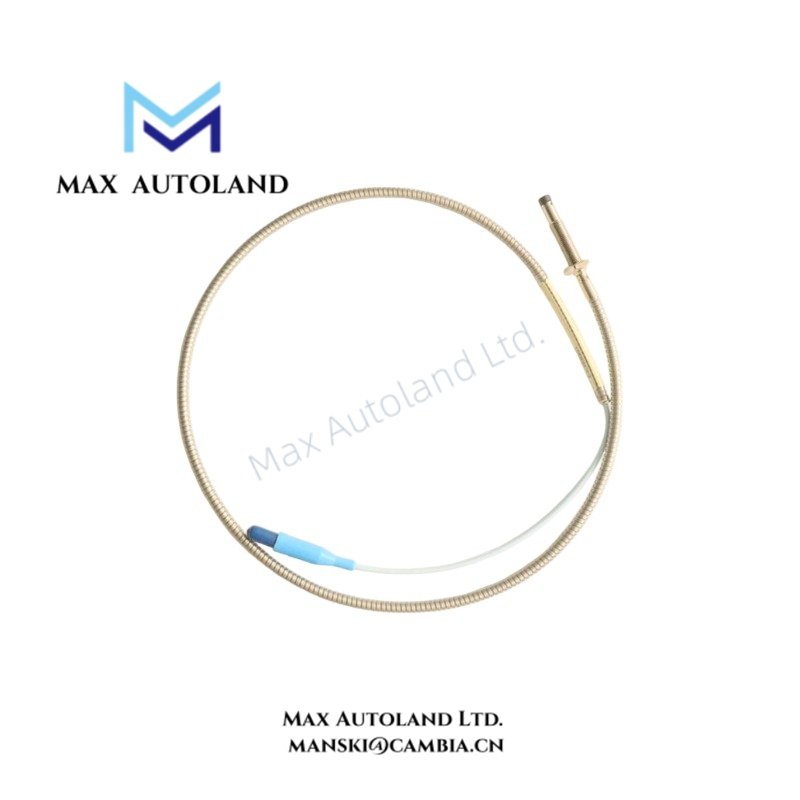
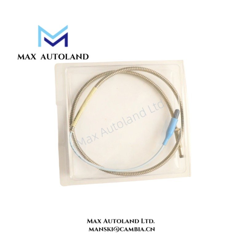
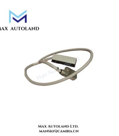
Configured for non-contact displacement measurement in the 3300 XL 8 mm Proximity Transducer System, the Bently Nevada 330104-00-09-05-11-05 (330104 Proximity Probe) converts probe-to-target distance into an electrical signal for static position and dynamic vibration monitoring.
Suffix Breakdown & Model Matrix
The supplied documentation identifies the following configuration elements for 330104-00-09-05-11-05. These details describe the provided configuration and should not be extended to other 330104 variants.
| Code | Specification |
|---|---|
| 330104 | 3300 XL 8 mm Proximity Probe |
| -00 | Unthreaded length option: 0.0 in |
| -09 | Overall case length option: 0.9 in |
| -05 | Total cable length: 0.5 m |
| -11 | Miniature coaxial ClickLoc connector with connector protector and FluidLoc cable |
| -05 | Multiple agency approval / hazardous-area certification option |
Hardware Specifications
| Parameter | Specification |
|---|---|
| Model | 330104-00-09-05-11-05 |
| Base Model | 330104 |
| Brand | Bently Nevada |
| Series | 3300 XL 8 mm |
| Product Type | Proximity Probe |
| Dimensions | Overall case length: 0.9 in; other dimensions not specified |
| Operating Temp | -35 deg C to +177 deg C |
| Storage Temp | -35 deg C to +177 deg C |
| Power Consumption | 12 mA maximum |
| Supply Voltage | -17.5 VDC to -26 VDC |
| Linear Scale Factor | 7.87 mV/um (200 mV/mil), +/- 6.5% typical |
| Linear Range | Approximately 2.0 mm (80 mils) |
| Measurement Range | Approximately 0.25 mm to 2.3 mm (10 to 90 mils) |
| Frequency Response | 0 to 6.5 kHz (+0, -3 dB) |
| Maximum Field Wiring | Up to 305 m (1000 ft) |
| Output Resistance | 50 ohm |
| Probe Tip Material | Polyphenylene sulfide (PPS) |
| Probe Case Material | AISI 304 stainless steel |
| Connector | Gold-plated brass ClickLoc connector |
| Cable | FluidLoc cable |
| Total Cable Length | 0.5 m |
| Target Material | Conductive steel |
| Recommended Shaft Diameter | 50.8 mm (2 in) or larger |
Eddy-Current Probe Scaling and Gap Measurement
The 330104-00-09-05-11-05 operates as part of an eddy-current proximity measurement chain. The probe senses the distance between its tip and a conductive target without physical contact. Consequently, shaft movement changes the electrical output.
The specified incremental scale factor is 7.87 mV/um, equivalent to 200 mV/mil. The nominal linear measurement range extends approximately 2.0 mm. The probe therefore supports both dynamic shaft vibration measurements and static shaft-position measurements when used with the appropriate Proximitor Sensor and monitoring system.
The specified frequency response reaches 6.5 kHz with field wiring up to 305 m. Installation should maintain the probe, extension cable, and Proximitor Sensor as a matched measurement chain.
Frequently Asked Questions
Q: What supply voltage does the 330104-00-09-05-11-05 require?
A: The probe system requires -17.5 VDC to -26 VDC and has a maximum stated consumption of 12 mA.
Q: What target does this proximity probe measure?
A: It measures displacement relative to a conductive target surface. The supplied specification identifies flat conductive steel targets and recommends a shaft diameter of at least 50.8 mm (2 in).
Q: What is the specified frequency response?
A: The specified frequency response is 0 to 6.5 kHz (+0, -3 dB) with field wiring up to 305 m.
Field Installation Guidelines
- Install the probe so its sensing axis faces the intended conductive target surface.
- Maintain the specified probe-to-target gap during mechanical installation and final adjustment.
- Use the probe with the corresponding Proximitor Sensor and compatible extension cable as a complete transducer chain.
- Route probe wiring separately from high-current power conductors where practical to reduce electrical interference.
- Maintain proper cable shielding and grounding practices according to the associated monitoring-system installation requirements.
- Secure the ClickLoc connector and cable routing so mechanical vibration does not impose unnecessary force on the connector or cable.
- Verify the target surface and shaft geometry before commissioning the measurement channel.
- Confirm the resulting gap voltage and signal response during commissioning before placing the monitoring channel into service.



Reviews
There are no reviews yet.