
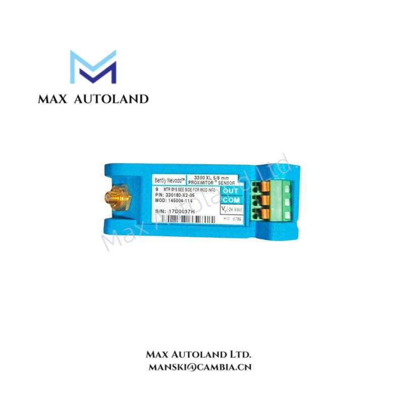
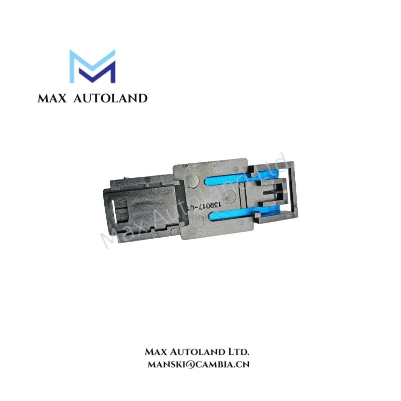

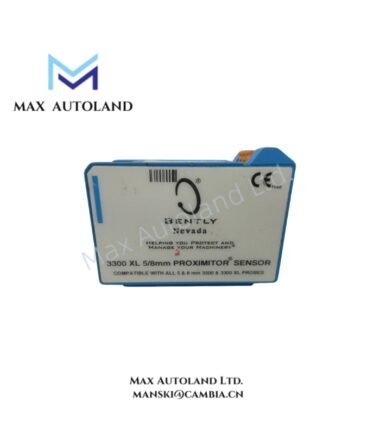

Overview
Suffix Breakdown & Model Matrix
The available documentation identifies the ordering code as 330180-X2-05. No official suffix allocation or ordering matrix is provided in the supplied information. The following catalog attributes are documented without assigning them to individual suffix positions:
| Parameter | Specification |
|---|---|
| Catalog Model | 330180-X2-05 |
| System Length Option | 1.0 m (3.3 ft) system length |
| Alternate System Length | 9.0 m (29.5 ft) system length |
| Mounting Hardware | No mounting hardware |
| Approvals | CSA, ATEX, IECEx |
Hardware Specifications
| Parameter | Specification |
|---|---|
| Model | 330180-X2-05 |
| Brand | Bently Nevada |
| Product Type | Proximitor Sensor |
| Manufacturer | Bently Nevada |
| Origin | USA |
| Shipping Location | Xiamen, China |
| Tariff Code | 8537101190 |
| Weight | 0.25 kg |
| Dimensions | 7.8 x 3 x 6.2 cm (estimated shipping size) |
| Operating Temp | Not specified |
| Power Consumption | Not specified |
| Measurement Principle | Eddy-current proximity sensing interface |
| System Length | 1.0 m (3.3 ft) configuration documented |
| Alternate Configuration | 9.0 m (29.5 ft) system length documented |
| Mounting Hardware | Not included |
| Certifications | CSA, ATEX, IECEx |
Eddy-Current Probe Scaling and Gap Voltage Validation
The Proximitor Sensor functions as the signal-conditioning element of an eddy-current proximity measurement chain. Correct operation depends on matching the Proximitor Sensor, extension cable, and proximity probe as a calibrated system length. During commissioning, gap voltage is typically verified against the target material before vibration measurements are accepted. For Bently Nevada eddy-current systems, gap voltage validation near -10 VDC is commonly used to confirm that the probe is operating within its calibrated linear measurement range. Proper cable routing and shielding also reduce cross-talk between adjacent probe channels in multi-channel machinery protection systems.
Frequently Asked Questions
Q: Can the Proximitor Sensor be exchanged independently of the probe assembly?
A: Replacement should maintain the specified calibrated probe, extension cable, and Proximitor Sensor combination. Mixing unmatched system components may affect calibration accuracy.
Q: Does the supplied unit include mounting hardware?
A: No. The provided product information specifies that mounting hardware is not included.
Q: What approvals are documented for this model?
A: The supplied specifications list CSA, ATEX, and IECEx approvals.
Field Installation Guidelines
- Verify the complete probe, extension cable, and Proximitor Sensor assembly matches the specified calibrated system length before installation.
- Route probe cables separately from high-energy power conductors to minimize electromagnetic coupling.
- Ground the cable shield according to the machinery monitoring system installation standard, avoiding multiple shield grounding points unless specified by the system design.
- Confirm gap voltage after mechanical installation and before placing the monitored machine into service.
- Do not sharply bend proximity probe extension cables or apply excessive tensile force during routing.
- Ensure the installation location allows adequate clearance for cable connectors and future maintenance access.







Reviews
There are no reviews yet.