
Overview
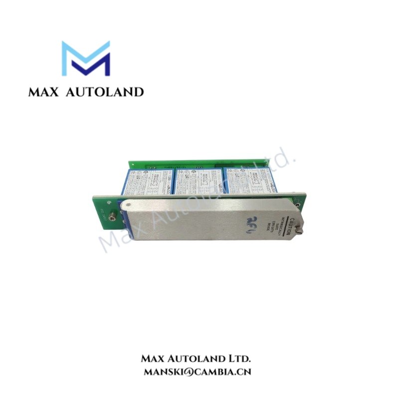
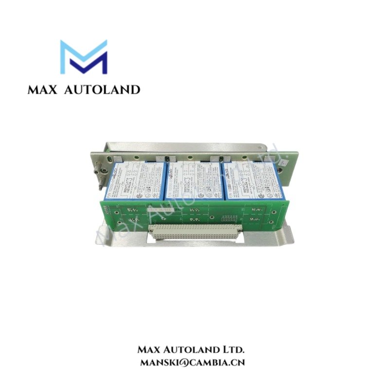
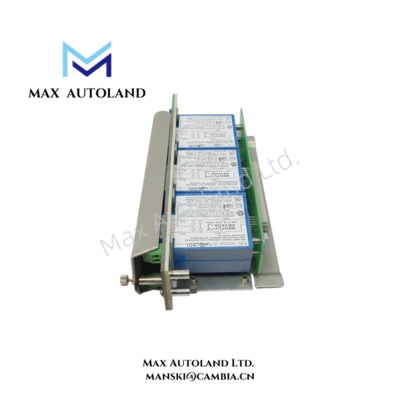
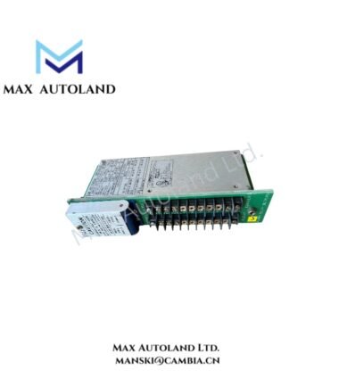
The Bently Nevada 102566-02, also cataloged as the 102566-02 RTD Input Module, provides direct acquisition and processing of resistance temperature detector signals. It accepts eight RTD input channels for temperature measurement on machinery components.
Hardware Specifications
| Parameter | Specification |
|---|---|
| Model | 102566-02 |
| Brand | Bently Nevada |
| Product Type | RTD Input Module |
| Origin | Not specified in supplied data |
| Number of Channels | 8 RTD input channels |
| Supported RTD Types | Pt100, Pt500, Pt1000 |
| Temperature Measurement Range | -200 deg C to +850 deg C |
| Resolution | 0.1 deg C |
| Accuracy | +/- 0.05% of reading |
| Operating Voltage | 24 VDC nominal |
| Power Consumption | 5 W |
| Communication Interface | HART protocol |
| Operating Temp | -40 deg C to +85 deg C |
| Certifications | CE, UL |
| Dimensions | 190 mm x 16.2 mm x 10.8 mm |
| Weight | 1.36 kg |
RTD Signal Acquisition and Machinery Monitoring
The 102566-02 receives resistance-based temperature signals from connected RTD elements. It supports Pt100, Pt500, and Pt1000 sensor types and converts the measured resistance into temperature data.
With eight input channels, the module can process multiple temperature points within the same monitoring arrangement. The specified measurement range extends from -200 deg C to +850 deg C, while the stated resolution is 0.1 deg C.
For machinery monitoring, RTD inputs can represent temperatures at bearings, gearboxes, motor windings, or other monitored points. Therefore, correct RTD type selection and sensor wiring are required to maintain the stated measurement characteristics.
Frequently Asked Questions
Q: How many RTD channels does the 102566-02 provide?
A: The supplied specification identifies eight RTD input channels.
Q: Which RTD elements are specified for the 102566-02?
A: The supplied data specifies Pt100, Pt500, and Pt1000 RTD types.
Q: Does the module support HART communication?
A: Yes. The supplied specification lists HART protocol support as its communication interface.
Field Installation Guidelines
- Verify the module part number and RTD sensor type before installation.
- Match each field RTD element with the corresponding input channel configuration.
- Keep RTD signal wiring separated from high-voltage power conductors and high-current switching circuits.
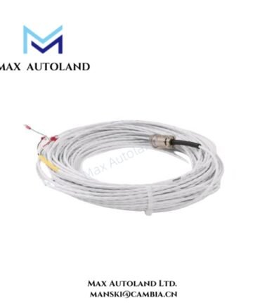
- Use appropriate shielded instrumentation cable where the installation requires noise control.
- Terminate cable shields according to the site grounding scheme and the applicable system installation documentation.
- Verify polarity, terminal assignment, and continuity before energizing the module.
- Confirm the nominal 24 VDC supply before applying power.
- Check the installed sensor range against the required temperature measurement range.
- After wiring, verify each channel with the connected RTD before placing the measurement point into service.



Reviews
There are no reviews yet.