

Overview
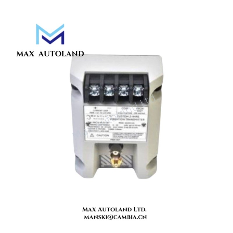
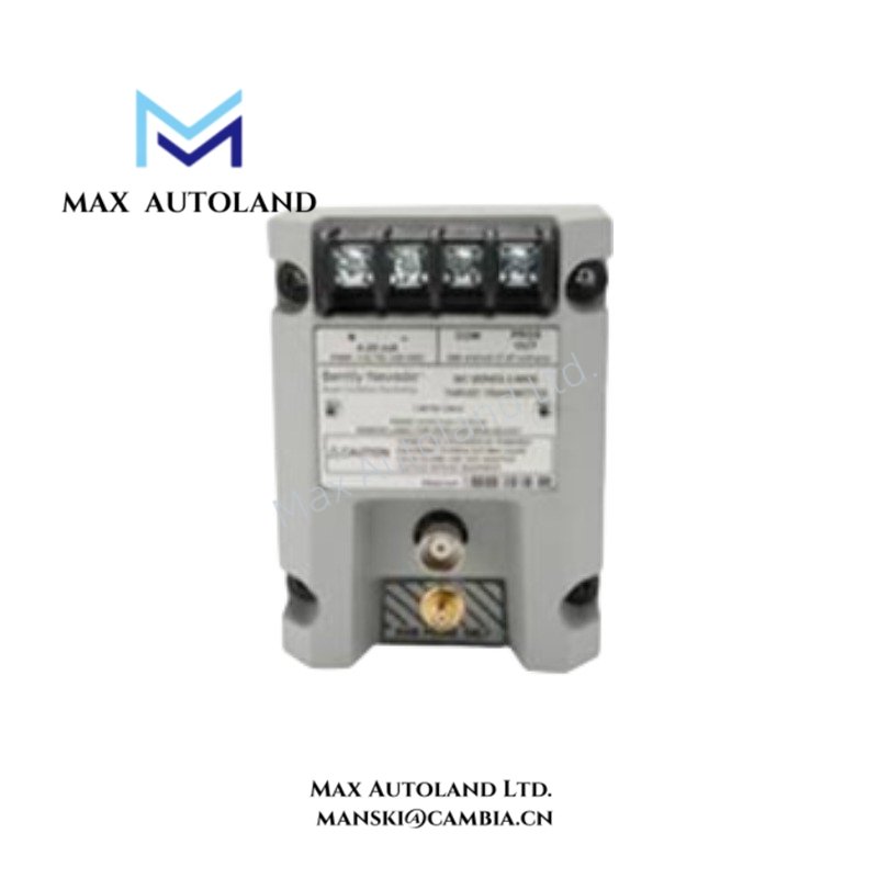
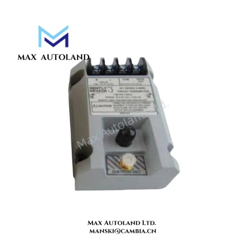
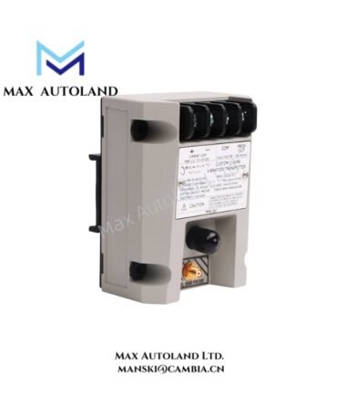
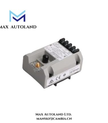
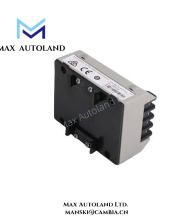
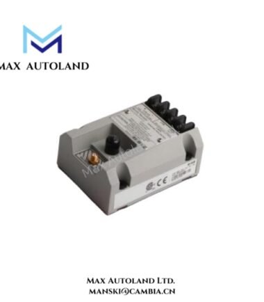
The Bently Nevada 990-08-XX-01-CN, also cataloged as the 990 vibration measurement transmitter, conditions a compatible proximity-probe signal into peak-to-peak vibration amplitude. It then sends a proportional 4-20 mAdc signal through a two-wire loop to the machinery control system. The specified full-scale range is 0-8 mils peak-to-peak.
Hardware Specifications
| Parameter | Specification |
|---|---|
| Model | 990-08-XX-01-CN |
| Brand | Bently Nevada |
| Product Type | Vibration Measurement Transmitter |
| Series | 990 Transmitter |
| Operating Temp | -35 to +85 deg C |
| Storage Temp | -52 to +100 deg C |
| Power Consumption | Not specified; supply is +12 to +35 Vdc at transmitter terminals |
| Full-Scale Range | 0-8 mils peak-to-peak |
| Signal Output | 4-20 mAdc, two-wire loop |
| Standard Transducer Input | One 3300 NSv probe and matching extension cable |
| Mounting | 35 mm DIN rail clips |
| Maximum Loop Resistance | 1000 ohm including cable at 35 Vdc |
| Typical Current Limiting | 23 mA |
| Not OK Output | Less than 3.6 mA within 100 microseconds |
| Not OK Recovery | 2-3 seconds after fault removal |
| Diagnostic Lead Limit | 3 m from Proximitor output BNC connector |
Eddy-Current Probe Signal Scaling
The 990-08-XX-01-CN accepts the signal from one compatible 3300 NSv proximity probe and its matching extension cable. The transmitter conditions the probe-system signal and represents vibration amplitude as a 4-20 mAdc loop current.
The selected measurement range is 0-8 mils peak-to-peak. Therefore, the installed probe, extension cable, and transmitter configuration must correspond to the specified measurement range. Before commissioning, verify the complete transducer chain rather than treating the transmitter as an independent measurement device.
The transmitter also provides a Not OK current response. When the specified fault condition occurs, the output falls below 3.6 mA within 100 microseconds. After fault removal, the output requires approximately 2-3 seconds to recover.
Frequently Asked Questions
Q: What proximity probe configuration does the transmitter require?
A: The supplied specification identifies one 3300 NSv probe with a matching extension cable as the standard transducer input. Verify the installed probe and cable against the transmitter configuration before replacement.
Q: What supply voltage does the transmitter require?
A: The transmitter operates from +12 to +35 Vdc at its terminals. The specified maximum loop resistance is 1000 ohm including cable at 35 Vdc.
Q: What happens when the transmitter detects a Not OK condition?
A: The output falls below 3.6 mA within 100 microseconds. After the fault clears, the specified recovery time is 2-3 seconds.
Field Installation Guidelines
- Mount the transmitter using the specified 35 mm DIN rail clips.
- Confirm the two-wire loop polarity before energizing the transmitter.
- Verify that the supply voltage remains within +12 to +35 Vdc at the transmitter terminals.
- Keep total loop resistance within the specified 1000 ohm maximum at 35 Vdc.
- Use the specified 3300 NSv probe and matching extension cable for the configured transmitter.
- Keep the diagnostic lead within the specified 3 m limit from the Proximitor output BNC connector.
- Route the vibration signal wiring separately from high-current switching conductors where practical to reduce electrical interference.
- Verify the probe, extension cable, transmitter range, and control-system scaling as one measurement chain before commissioning.
- Set the zero and span through the external adjustments only after confirming the connected probe system and receiving-loop configuration.





Reviews
There are no reviews yet.