Overview
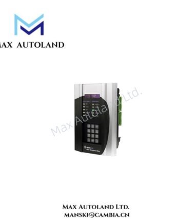
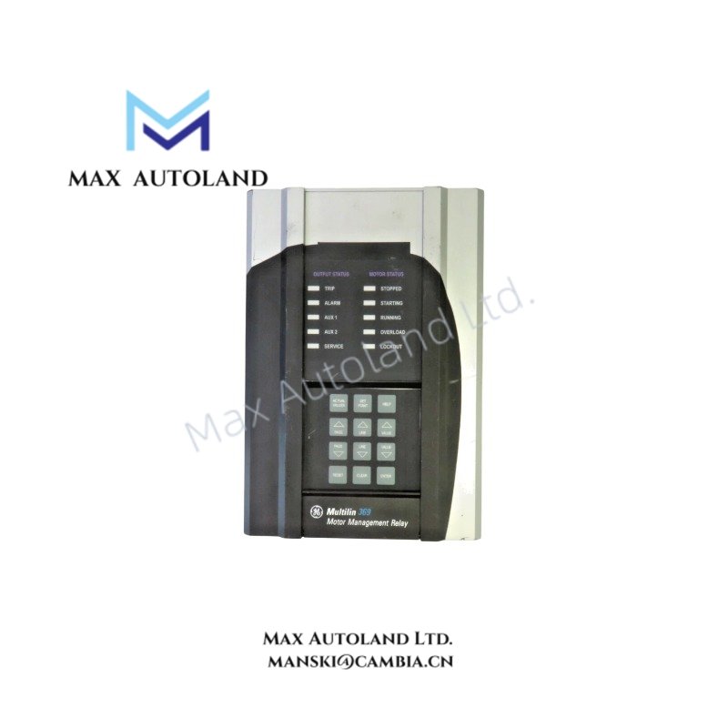
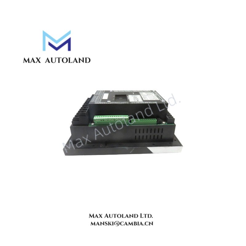
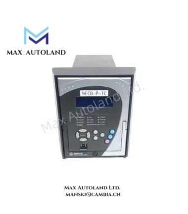
Configured for three-phase motor protection and operational monitoring in industrial control networks, the GE 369-HI-0-0-0-0-0-E (369 Motor Management Relay) provides direct electrical execution of thermal overload protection, current sensing, and event recording functions.
Suffix Breakdown & Model Matrix
| Code Segment | Definition |
|---|---|
| 369 | Base Motor Management Relay unit |
| HI | High Voltage Control Power (50–300 VDC / 60–265 VAC) |
| 0 | No optional 12 RTD inputs |
| 0 | No optional metering package |
| 0 | No optional fiber optic port |
| 0 | No optional protocol interfaces |
| 0 | No optional hardware variations |
| E | Enhanced faceplate with diagnostics, audit trail, expanded event recorder |
Hardware Specifications
| Parameter | Specification |
|---|---|
| Brand | GE Multilin |
| Origin | Canada |
| Weight | 8–10 lb (3.6–4.5 kg) |
| Dimensions | 11.5 in x 5.5 in x 8.5 in (29.5 cm x 13.0 cm x 20.5 cm) |
| Operating Temp | -40 degC to +60 degC |
| Power Consumption | 50–300 VDC / 60–265 VAC, 3.15 A fuse rating |
| Phase Current Input | 1 A and 5 A secondary CTs |
| Ground Current Frequency | 20–100 Hz |
| Ingress Protection | IP50X |
Firmware Flash Compatibility
The 369 series supports firmware updates via the front-panel RS232 service port using EnerVista 369 Setup Software. Flash operations require stable control power within specified voltage tolerance to prevent corruption of non-volatile memory sectors. Backward compatibility is maintained between major firmware revisions, but feature activation depends on hardware option flags encoded in the unit’s EEPROM.
Frequently Asked Questions
Q: Can the relay be installed without removing motor power?
A: No. Control power and CT circuits must be de-energized before installation to avoid arc flash hazards and ensure accurate calibration of current transformers.
Q: Does the enhanced event recorder retain data during power loss?
A: Yes. Event records and motor health statistics are stored in non-volatile memory, surviving complete control power outages.
Q: Is external communication isolation required for RS485 ports?
A: External isolation devices are recommended when connecting to third-party systems to prevent ground loop-induced communication errors.
Field Installation Guidelines
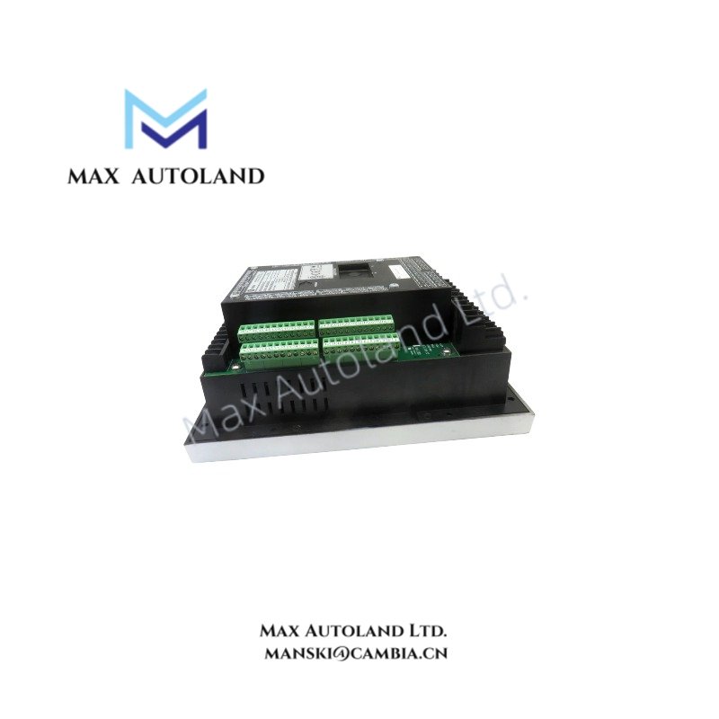
Mount the relay in a vertical orientation inside a grounded metal enclosure to maintain operating temperature limits. Use separate conduit runs for control wiring and current transformer leads to minimize electromagnetic interference. Terminate all shielded cable drains to the enclosure ground bus using approved grounding clamps. Verify CT polarity before applying load current to prevent incorrect thermal model calculations. Tighten all terminal screws to manufacturer torque specifications and confirm secure seating of the faceplate connector prior to energization.