
Overview
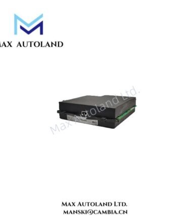
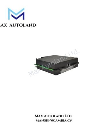
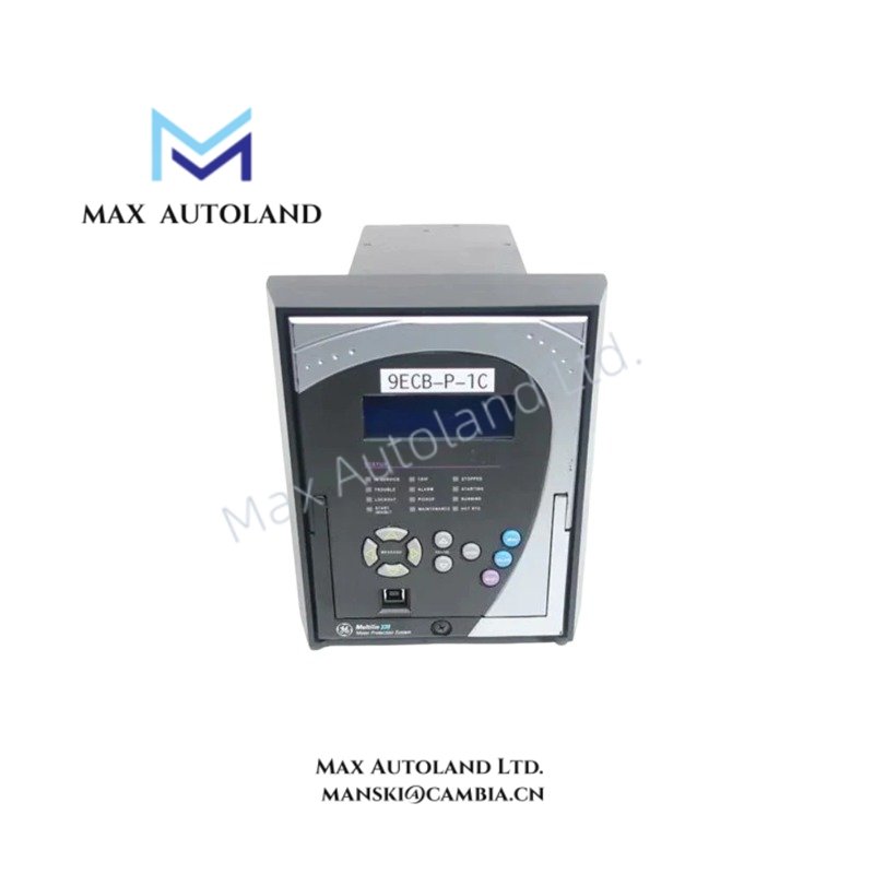
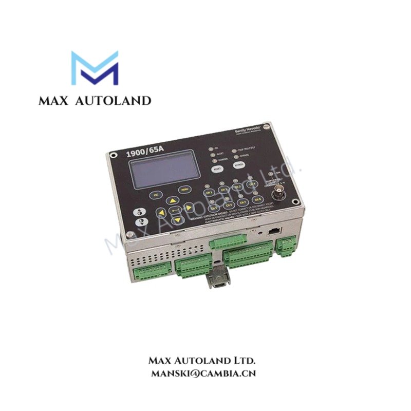
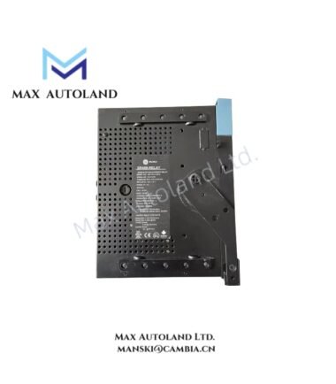
Configured for motor protection logic execution in industrial automation networks, the GE 369B1875G0003 (base model 369) Motor Management Relay provides direct physical interruption of motor supply circuits upon detection of electrical and thermal anomalies.
Suffix Breakdown & Model Matrix
| Parameter | Specification |
|---|---|
| Model Brand | GE Multilin |
| Origin | United States |
| Weight | 0.5 kg |
| Dimensions | 96 mm x 96 mm x 120 mm |
| Operating Temp | -40 degC to +70 degC |
| Power Consumption | 230 V AC |
Hardware Specifications
| Parameter | Specification |
|---|---|
| Device Type | Motor Management Relay / Motor Protection Relay |
| Rated Voltage | 230 V AC RMS |
| Rated Current | 100 A (Nominal Primary CT Input) |
| Frequency | 50/60 Hz |
| Protection Functions | Thermal Overload, Locked Rotor, Phase Unbalance, Ground Fault, Undervoltage, Overvoltage |
| Mounting Type | DIN Rail / Panel Flush Mount |
| Enclosure Rating | IP40 (Front Panel IP54 with Optional Gasket) |
| Communication Protocol | Modbus RTU (RS485) |
Backplane Bus and Firmware Compatibility
The 369B1875G0003 utilizes a deterministic backplane bus architecture for integration into GE Multilin networked systems. The “G0003” suffix denotes a specific hardware revision and firmware package. Interoperability requires matching firmware revisions between replacement units to maintain consistent logic execution and parameter scaling. Mismatched firmware may result in altered timing delays for start-per-hour limitations or restart sequences.
Frequently Asked Questions
Q: Does the 369B1875G0003 support hot-swapping while the motor control center is energized?
A: No. The device must be de-energized prior to removal or installation to prevent arcing and damage to the terminal blocks and internal circuitry.
Q: What is the impact of firmware mismatch during unit replacement?
A: Firmware mismatches can cause parameter translation errors, specifically in thermal model calculations and communication protocol data mapping.
Q: Is the RS485 port galvanically isolated from the power supply terminals?
A: Yes. The communication circuit includes isolation to prevent ground loops when interfacing with external PLC or DCS networks.
Field Installation Guidelines
Mount the relay to a standard DIN rail or directly to the panel using the provided flush-mount hardware. Ensure torque specifications are met for all power and CT connections to prevent resistive heating. Terminate the RS485 communication shield at one end only, typically at the host controller, to avoid ground potential differences. Verify that the CT wiring polarity matches the relay’s phase sequence to ensure accurate current measurement and phase unbalance detection.