


Overview
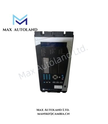
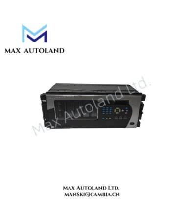
The GE Multilin G60E00HUHF8LH6UMXXPXXUXXWXX, also cataloged as the G60 Generator Protection System, operates as a dedicated hardware component for generator protection, control, and electrical signal processing within GE Multilin Universal Relay (UR) platforms.
Hardware Specifications
| Parameter | Specification |
|---|---|
| Model | G60E00HUHF8LH6UMXXPXXUXXWXX |
| Brand | GE Multilin |
| Origin | GE Universal Relay (UR) Series |
| Product Type | Generator Protection System |
| Dimensions | 19-inch rack mount chassis, 4RU height |
| Operating Temp | -40 deg C to +60 deg C |
| Storage Temp | -40 deg C to +85 deg C |
| Power Consumption | Not specified in available documentation |
| Power Supply | High voltage input, 88-300 VDC or 88-265 VAC, 50/60 Hz |
| CPU Module | Standard CPU with RS485 and Ethernet communication |
| Front Panel Interface | Graphical color LCD display, LEDs, and navigation keypad |
| CT Inputs | 1 A or 5 A nominal secondary current transformer inputs |
| VT Inputs | 50-240 VAC phase-to-neutral voltage transformer inputs |
| Communication Protocols | IEC 61850, Modbus RTU, Modbus TCP/IP, DNP 3.0 |
| Communication Ports | Front USB/RS232, rear RJ45 Ethernet, RS485 |
| Slot F Module | CT/VT DSP module for current and voltage measurement |
| Slot H Module | Digital I/O module with Form-A/Form-C contacts and digital inputs |
| Slot M/P/U/W Modules | Unpopulated slots |
GE Multilin UR Platform Communication and Control Features
The GE Multilin G60 uses the UR platform architecture to process generator electrical measurements, execute protection logic, and control trip outputs. The relay receives CT and VT signals through dedicated sensing modules. In addition, it communicates with substation systems through IEC 61850, Modbus, and DNP 3.0 protocols.
The FlexLogic programming engine allows users to configure custom control schemes, trip matrices, permissive logic, and interlocking functions without an external PLC. Furthermore, the relay supports deterministic signal processing through its embedded CPU architecture and firmware-based control execution.
The G60 supports generator protection functions including:
- Generator differential protection (87G) with CT saturation detection
- 100% stator ground fault protection (59N / 27TN)
- Loss of excitation protection (40)
- Volts per Hertz overexcitation protection (24)
- Reverse power anti-motoring protection (32R / 32)
- Negative sequence current protection (46)
- Phase distance backup protection (21P)
- Overfrequency and underfrequency protection (81O / 81U)
- Overvoltage and undervoltage protection (59 / 27)
- Accidental energization protection (50 / 27)
- Breaker failure protection (50BF)
- Synchronism check function (25)
Frequently Asked Questions
Q: Does the GE Multilin G60 support IEC 61850 communication?
A: Yes. The G60 supports IEC 61850 communication together with Modbus RTU, Modbus TCP/IP, and DNP 3.0 protocols through integrated communication interfaces.
Q: What CT and VT inputs does the G60 accept?
A: The relay accepts 1 A or 5 A CT secondary inputs and voltage transformer inputs from 50-240 VAC phase-to-neutral signals.
Q: Can the G60 execute custom protection and control logic?
A: Yes. The integrated FlexLogic engine allows configuration of protection coordination, trip logic, interlocking, and control sequences inside the relay firmware.
Field Installation Guidelines
- Install the G60 in a suitable 19-inch rack enclosure with correct mechanical support for the 4RU chassis.
- Connect CT circuits using dedicated shielded wiring and verify correct polarity before energizing the relay.
- Maintain separation between CT/VT signal wiring and high-voltage power cables to reduce electromagnetic interference.
- Ground cable shields according to site protection standards and maintain a low impedance grounding path.
- Verify VT secondary voltage levels before applying measurement inputs to the relay terminals.
- Confirm communication settings, including IP parameters, RS485 wiring polarity, and protocol configuration, before integration with the substation network.
- Perform functional testing of trip outputs, breaker failure logic, synchronism check, and protection elements before placing the generator protection system into service.


