Overview
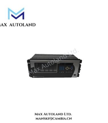
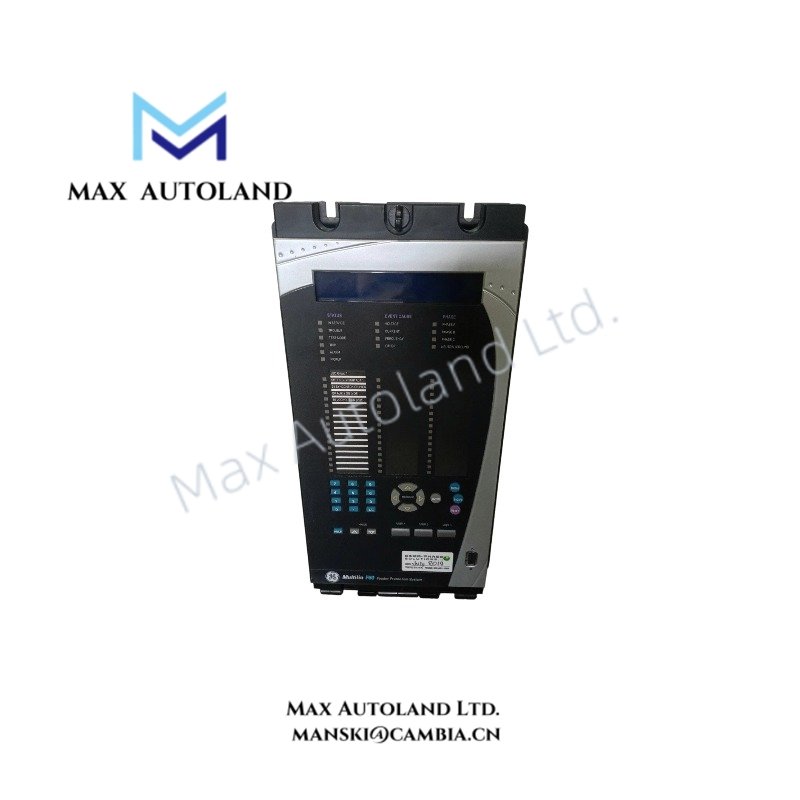
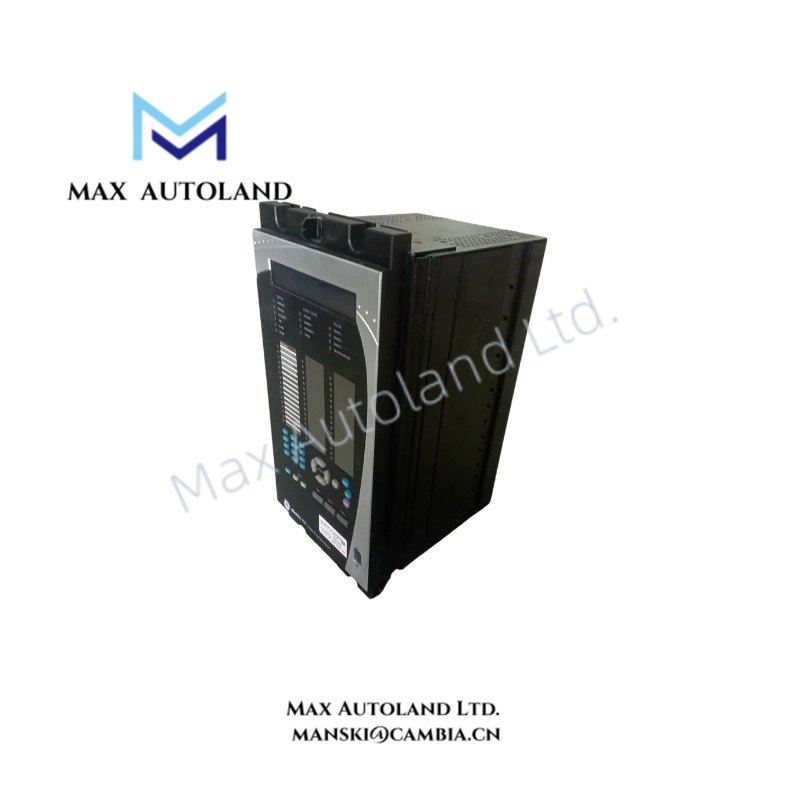
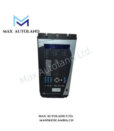
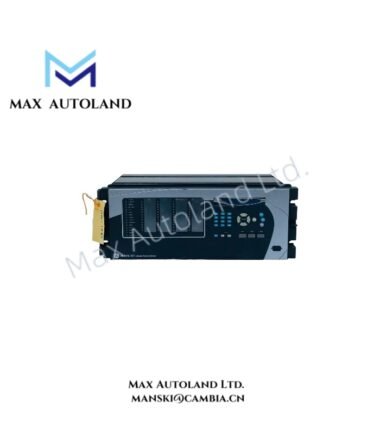
Configured for generator fault protection and measurement processing in the GE Multilin Universal Relay platform, the GE Multilin G60-N00-HUH-F8L-H6T-M8L-P6C-U6C-W6C (G60 Generator Protection System) provides direct electrical signal acquisition, protection logic execution, and control output management.
Hardware Specifications
| Parameter | Specification |
|---|---|
| Model | GE Multilin G60-N00-HUH-F8L-H6T-M8L-P6C-U6C-W6C |
| Brand | GE Multilin |
| Origin | General Electric Universal Relay Platform |
| Product Type | Generator Protection Systems |
| Dimensions | Standard GE Multilin UR full rack chassis |
| Operating Temp | -40 deg C to +60 deg C |
| Power Consumption | Not specified in available technical data |
| Control Power Supply | 125-250 VDC / 100-240 VAC, 50/60 Hz |
| CT Inputs | 1 A or 5 A secondary current inputs |
| VT Inputs | 50-240 V AC nominal voltage inputs |
| Communication Interfaces | IEC 61850, Modbus RTU/TCP, DNP 3.0 |
| Data Recording | Event recording, oscillography, fault location functions |
| Mounting Configuration | 19-inch rack mount UR chassis |
GE Multilin Generator Protection Processing and Control Functions
The GE Multilin G60 processes generator electrical measurements through CT and VT input modules, then applies protection algorithms for fault detection and trip control. The relay executes generator differential protection (87G), stator earth fault protection (27TN/59N), loss of excitation protection (40), reverse power protection (32), and volts-per-hertz protection (24).
Furthermore, the G60 applies backup protection elements including phase distance protection (21), voltage restrained overcurrent protection (51V), and phase overcurrent protection (50/51). The relay also monitors frequency and voltage conditions through over/under frequency (81O/81U) and over/under voltage (27/59) elements.
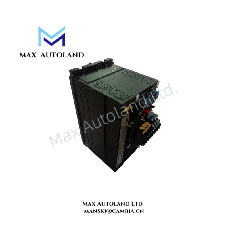
The configured hardware includes CT/VT measurement modules, digital input modules, and output relay modules. Therefore, the unit supports generator status monitoring, breaker control circuits, and protective trip output execution within the Universal Relay architecture.
Frequently Asked Questions
Q: Does the GE Multilin G60-N00-HUH-F8L-H6T-M8L-P6C-U6C-W6C support direct generator current and voltage measurement?
A: Yes. The configured F8L and M8L modules provide CT and VT measurement interfaces for generator protection calculations.
Q: Can the G60 operate with different control power systems?
A: Yes. The specified power supply module supports 125-250 VDC and 100-240 VAC input sources.
Q: Which communication protocols can the G60 exchange data with?
A: The relay supports IEC 61850, Modbus RTU/TCP, and DNP 3.0 communication interfaces for system integration.
Field Installation Guidelines
Install the GE Multilin G60 relay in a suitable protective enclosure with correct grounding and ventilation arrangements. Connect CT secondary circuits using dedicated terminal wiring and maintain proper polarity between current transformers and relay inputs.
Use shielded communication cables for serial and Ethernet connections where required by the installation environment. Ground cable shields according to the site grounding practice to reduce electromagnetic interference.
Verify VT and CT wiring before energizing the relay. Confirm that measured current, voltage, frequency, and phase sequence values match the generator protection configuration.
Check digital input voltage levels and output relay contact wiring before commissioning. Perform functional testing of protection elements, trip outputs, and communication links after installation.