
Overview
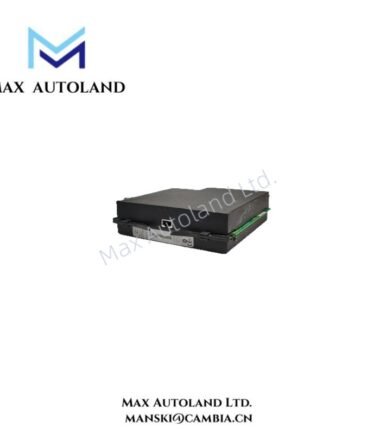
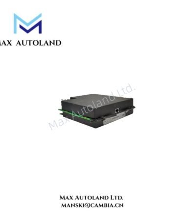
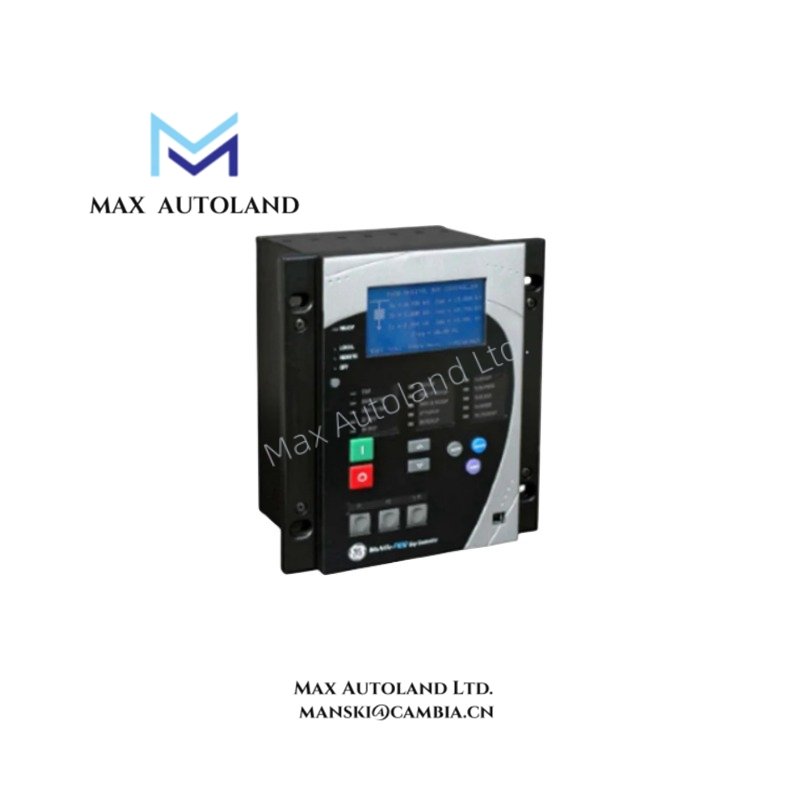
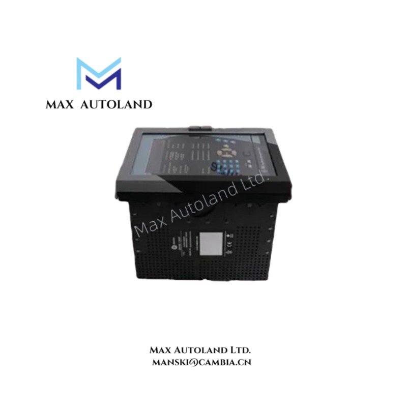
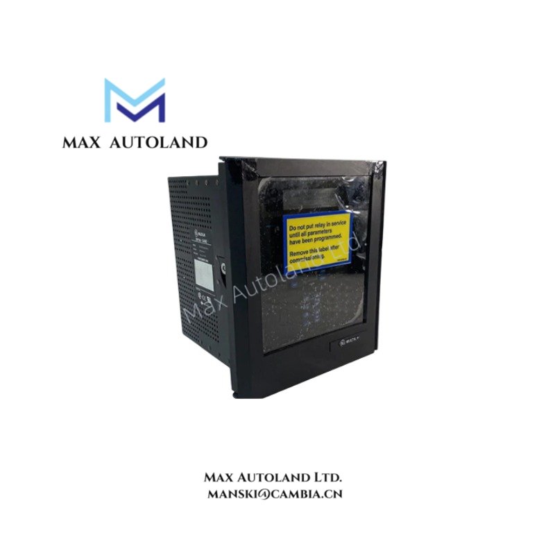
The GE F650BFEF1G0HHI, also cataloged as the F650 Feeder Protection and Control System, operates as a dedicated hardware component for protection, control, and monitoring of distribution feeders, transformers, and transmission lines within substation automation networks.
Suffix Breakdown & Model Matrix
| Code Position | Character | Specification |
|---|---|---|
| Base Model | F650 | Multilin F650 Feeder Protection System |
| Language | B | English / French (Standard Dual Language) |
| Phase CTs | F | 5 A Phase Current Transformers (CTs) |
| Ground CT | E | 1 A Ground/Earth Current Transformer (CT) |
| Power Supply | F | 110 – 250 VDC / 120 – 230 VAC |
| Slot F (I/O) | 1 | 8 Digital Inputs + 8 Digital Outputs |
| Slot G (I/O) | G | 16 Digital Inputs |
| Slot H (I/O) | 0 | Empty / No I/O board in Slot H |
| Slot I (Comm) | H | Redundant 10/100 Base TX (RJ45) Ethernet interfaces |
| Slot J (Audio/Misc) | H | Standard Option / None |
| Software Options | I | Enhanced Protection & Control Functions |
Hardware Specifications
| Parameter | Specification |
|---|---|
| Model | F650BFEF1G0HHI |
| Brand | General Electric (GE) |
| Series | Multilin F650 |
| Phase CT Rating | 5 A |
| Ground CT Rating | 1 A |
| Power Supply Voltage | 110 – 250 VDC / 120 – 230 VAC |
| Digital Inputs | 24 (8 in Slot F + 16 in Slot G) |
| Digital Outputs | 8 (Form-A/Form-C relays) |
| Communication Ports | Redundant 10/100 Base-TX Ethernet (RJ45) |
| Supported Protocols | Modbus RTU/TCP, DNP 3.0, IEC 60870-5-103/104, IEC 61850 |
| Front Panel | Graphical LCD display, navigation keys, LED status indicators |
| Enclosure Size | 4U half-rack horizontal chassis |
| Mounting | Panel or rack mountable |
| Operating Temperature | -20 deg C to +60 deg C |
| Ingress Protection | IP52 (Front panel) |
Backplane Bus Communication and I/O Scaling
The F650 utilizes a high-speed backplane bus architecture to manage data exchange between the CPU, I/O modules, and communication interfaces. The slot-based I/O configuration (Slots F, G, H) allows for deterministic scanning of digital inputs and outputs. With 24 digital inputs and 8 digital outputs, the system supports distributed control logic execution directly at the bay level. The redundant Ethernet ports in Slot I provide dual-path communication for substation automation networks, supporting IEC 61850 GOOSE messaging for peer-to-peer protection signaling with minimal latency.
Frequently Asked Questions
Q: What is the total digital I/O capacity of the F650BFEF1G0HHI configuration?
A: The unit provides 24 digital inputs (8 in Slot F + 16 in Slot G) and 8 digital outputs (in Slot F), totaling 32 I/O points for protection and control functions.
Q: Does the F650BFEF1G0HHI support IEC 61850 protocol?
A: Yes, the redundant Ethernet interfaces (Slot I, code H) support IEC 61850 with GOOSE messaging capabilities for substation automation integration.
Q: What are the power supply requirements for this model?
A: The unit operates on 110-250 VDC or 120-230 VAC, with tolerance ranges of approximately 88-300 VDC and 85-264 VAC respectively.
Field Installation Guidelines
- Mounting: Install the 4U half-rack chassis in a standard 19-inch rack or panel mount configuration. Ensure adequate clearance for ventilation around the unit.
- Grounding: Connect the ground terminal to the substation earth grid using a minimum 4 AWG copper conductor. Verify ground impedance is less than 1 ohm.
- CT Wiring: Connect phase CTs to the 5 A inputs and ground CT to the 1 A input. Ensure CT secondaries are terminated in their rated burden to prevent saturation.
- Ethernet Cabling: Use shielded Cat5e or Cat6 cables for the redundant Ethernet connections. Maintain separation from power cables to minimize EMI.
- Digital I/O Wiring: Route control cables separately from power wiring. Use twisted pair conductors for digital inputs to reduce noise pickup.
- Commissioning: After installation, verify all CT polarity connections, test digital output relay operation, and confirm communication link status via the front panel LCD.