Overview
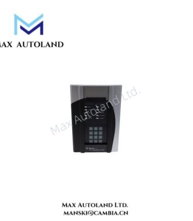
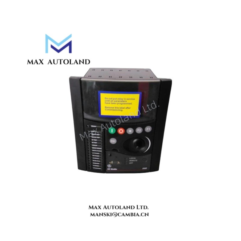
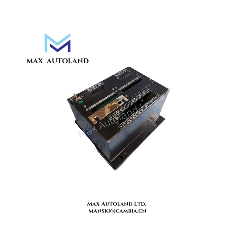
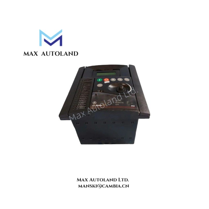
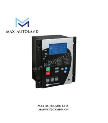
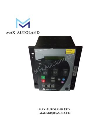
The GE Multilin F650MFBF2G0HI, also cataloged as the F650 feeder management relay, operates as a dedicated hardware component for protection, control, and monitoring of distribution feeders within substation automation networks.
Suffix Breakdown & Model Matrix
| Position | Code | Description |
|---|---|---|
| Base Series | F650 | Feeder Management Relay |
| M | Software | Protection + Control + Metering + Digital Fault Recorder + IEC 61850 |
| F | Display | Enhanced Graphical Text Display (English) |
| B | Rear Comm | 10/100 BaseT Ethernet + RS485 + RS232 |
| F | Slot F (I/O) | 8 Digital Inputs + 8 Outputs (Form-C Relays) |
| 2 | Slot G (I/O) | 4 Current Inputs (1A/5A) + 4 Voltage Inputs + 8 Digital Inputs |
| G | Slot H (I/O) | 16 Digital Inputs |
| 0 | Slot I (I/O) | None / Empty |
| H | Power Supply | 110-250 VDC / 120-230 VAC |
| I | Coating | Harsh Environment Conformal Coating |
Hardware Specifications
| Parameter | Specification |
|---|---|
| Model | F650MFBF2G0HI |
| Brand | GE – General Electric |
| Origin | Webster, NY, USA |
| Weight | 8 lbs 14.4 oz (4.0 kg) |
| Dimensions | 9.3 in x 10.5 in x 7.3 in (23.5 cm x 26.7 cm x 18.4 cm) |
| Power Supply | 110-250 VDC / 120-230 VAC (50/60 Hz) |
| Analog Inputs | 4 Current Channels (1A/5A CT), 4 Voltage Channels (VT) |
| Digital Inputs | 32 total (wet/dry contacts) |
| Digital Outputs | 8 Form-C Relays |
| Protection Class | IP54 (front panel) |
| Enclosure | 4U half-rack chassis |
Protection & Control Functions
| Function | Element |
|---|---|
| Phase Overcurrent | 50P (Instantaneous), 51P (Time Delay) |
| Ground/Earth Overcurrent | 50G/51G, 50N/51N |
| Directional Elements | 67P (Phase), 67N/67G (Ground) |
| Voltage Protection | 59 (Overvoltage), 27 (Undervoltage), 59N (Displacement) |
| Frequency Protection | 81O (Overfrequency), 81U (Underfrequency), 81R (ROCOF) |
| Control Functions | 79 (Autoreclose), 50BF (Breaker Failure), 25 (Synchrocheck) |
Communication Protocols & Backplane Integration
The F650MFBF2G0HI interfaces with substation control networks via Modbus RTU, Modbus TCP/IP, DNP 3.0, and IEC 61850 with GOOSE messaging support. The rear panel provides RJ45 Ethernet and RS485 terminals for deterministic data exchange across the backplane bus. Front panel access is available through RS232 or USB for local configuration via EnerVista software.
Frequently Asked Questions
Q: What is the maximum analog sampling resolution for fault recording?
A: The integrated Digital Fault Recorder (DFR) captures up to 64 samples per cycle for waveform analysis.
Q: Does the relay support hot-swap capability for I/O modules?
A: No. The I/O boards are internally mounted and not field-replaceable without unit removal from the panel.
Q: What is the event logging resolution?
A: Sequence of Events (SOE) logging provides 1 millisecond time-stamped resolution.
Field Installation Guidelines
- Mount in a 4U half-rack panel cutout with secure mechanical fastening on all four corners.
- Ensure the rear communication cables (Ethernet/RS485) are routed separately from high-voltage CT/VT wiring to minimize electromagnetic interference.
- Verify CT secondary wiring polarity before energizing the current inputs. Incorrect polarity will cause directional protection elements (67P/67N) to operate incorrectly.
- Apply proper torque to all terminal block screws per GE’s torque specifications. Loose connections on CT circuits can result in open-circuit conditions exceeding safe voltage limits.
- Allow adequate clearance at the rear for Ethernet and serial cable bend radius. The conformal coating (Option I) provides additional protection against moisture and corrosive atmospheres but does not eliminate the need for proper enclosure sealing.