Overview
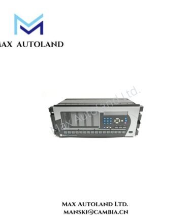
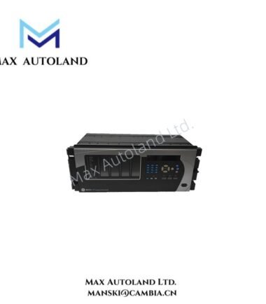
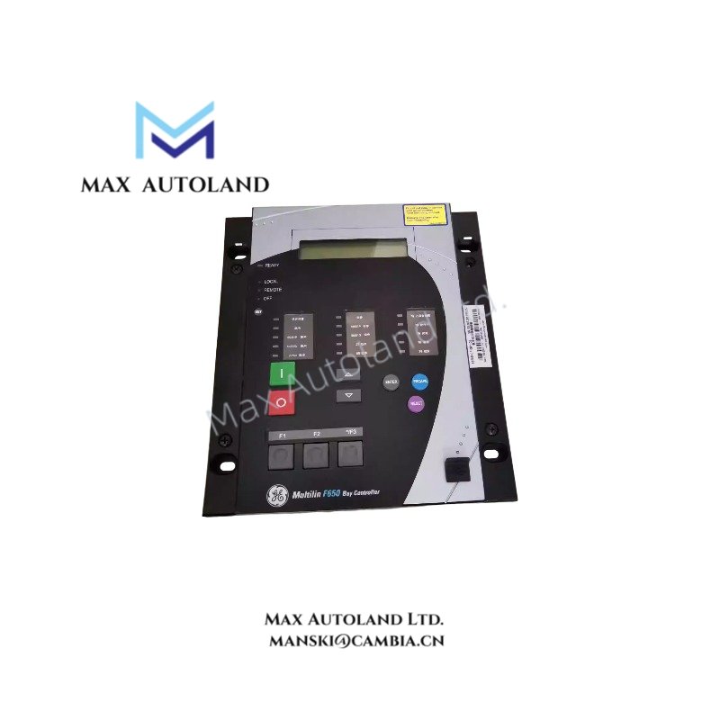
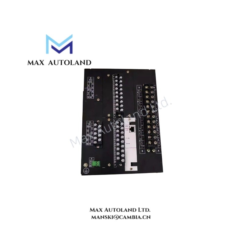
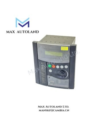
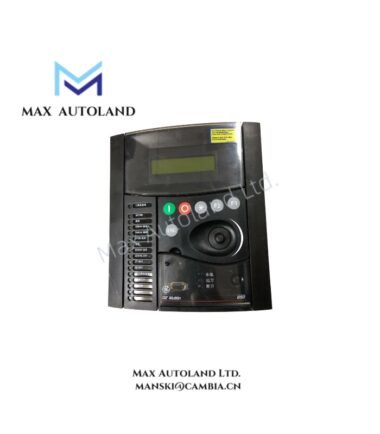
The GE F650BFBF1G0HICE, also cataloged as the F650 Controller Relay Module, operates as a dedicated hardware component for feeder protection, control logic execution, and automation signaling within power management infrastructures. It processes phase and ground current inputs, executes overcurrent algorithms, and transmits status data via integrated communication ports for industrial electrical network operation.
Suffix Breakdown & Model Matrix
| Position | Code | Definition |
|---|---|---|
| Base Model | F650 | Feeder Management Relay |
| Power Supply | F | 48-125 VDC / 110-120 VAC |
| Phase CT Inputs | B | 5 A / 1 A Selectable |
| Ground CT Inputs | F | 5 A / 1 A Selectable |
| Slot F Option | 1 | 16 Digital Inputs + 8 Digital Outputs |
| Slot G Option | G | 8 Digital Inputs + 8 Digital Outputs + 4 Analog Inputs + 2 Analog Outputs |
| Slot H Option | 0 | Empty Slot |
| Front Panel | H | Enhanced LCD Graphic Display |
| Communication | I | Redundant Ethernet + RS485 |
| Protocol | C | IEC 61850, Modbus TCP/RTU, DNP 3.0 |
| Coating | E | Harsh Environment Conformal Coating |
Hardware Specifications
| Parameter | Specification |
|---|---|
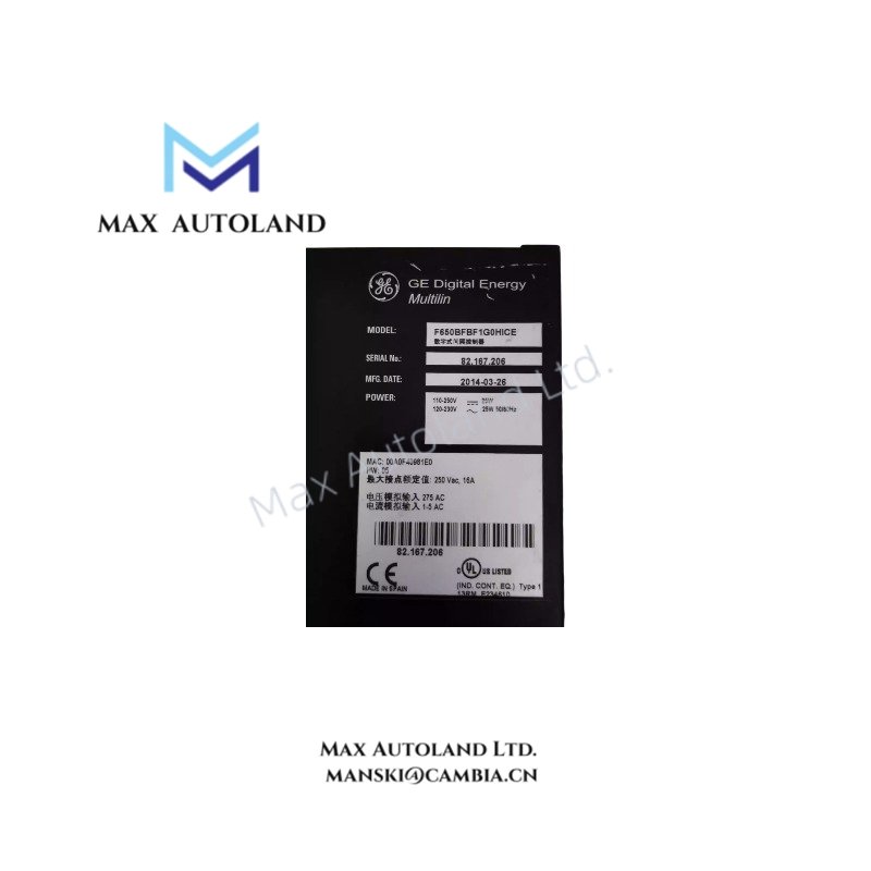
| Model | F650BFBF1G0HICE |
| Brand | GE Multilin |
| Origin | United States |
| Weight | Approx. 2.5 kg |
| Dimensions | 177.8 mm x 254 mm x 228.6 mm |
| Operating Temp | -40 deg C to +70 deg C |
| Power Consumption | 15 W typical at nominal voltage |
| Protection Functions | 50/51, 67, 79, 81, 49 |
| Communication Ports | 10/100 BaseTX Ethernet, RS485 |
| Mounting | Panel or 19-inch rack mount |
Firmware Flash and Backplane Bus Behavior
The F650 series utilizes deterministic backplane bus communication for inter-module data exchange. Firmware flash compatibility requires matching hardware revision levels to prevent configuration upload errors. I/O density scaling allows expansion through multiple slot configurations without altering base CPU logic. Profinet and EtherNet/IP deterministic networks are not native; protocol selection is fixed by ordering code.
Frequently Asked Questions
Q: Does the F650BFBF1G0HICE support hot-swap replacement without system shutdown?
A: No. The module must be de-energized prior to removal or installation to avoid backplane damage and loss of protection continuity.
Q: What is the maximum analog input burden for the 4-20 mA channels in Slot G?
A: Each analog input presents a 250 ohm burden, limiting loop-powered transmitter drive capacity to 24 VDC supply compliance.
Q: Are redundant Ethernet ports capable of automatic failover without relay restart?
A: Yes. Port switching occurs within the communication stack without interrupting protection processing.
Field Installation Guidelines
Mount the relay in a clean, vibration-free panel location using secure fixing points. Maintain minimum clearance of 50 mm above and below the unit for ventilation. Use shielded twisted-pair cabling for all current transformer and communication connections, grounding shields at the relay end only. Verify torque values of terminal screws to 0.8 Nm. Prior to energizing, confirm conformal coating integrity and absence of conductive debris.