
Overview
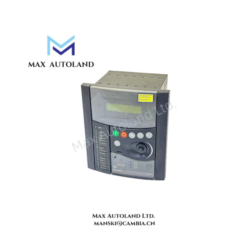
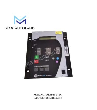
The GE Multilin F650BFBF1G0HIC, also cataloged as the F650 Feeder Protection Relay and Bay Controller, operates as a dedicated hardware component for protection, control, and automation of distribution feeders and substation bays within SCADA and substation automation networks.
Suffix Breakdown & Model Matrix
| Suffix | Designation | Description |
|---|---|---|
| F650 | Base Unit | Feeder Protection Relay and Bay Controller |
| B | Phase / Ground CT | 5A / 1A dual rated |
| F | Protection & Control | Standard Protection Functions + Control Functions (Breaker Control, Logic) |
| B | Faceplate / Display | English language / Standard display with text and single line diagrams |
| F | I/O Card Slot | Configured with digital inputs / outputs |
| 1 | Cyber Security | Standard cyber security features enabled |
| G | Communication Card 1 | Redundant Ethernet / Protocol options |
| 0 | Communication Card 2 | None |
| H | Power Supply | High voltage range (110 – 250 VDC / 110 – 230 VAC) |
| I | Insulation / Environment | Standard conformal coating / environmental compliance |
| C | Harsh Environment | Conformal coating on boards for moisture and chemical resilience |
Hardware Specifications
| Parameter | Specification |
|---|---|
| Model | F650BFBF1G0HIC |
| Brand | GE Vernova / Grid Solutions (General Electric) |
| Current Inputs (CTs) | 1A / 5A software programmable, phase and ground |
| Voltage Inputs (VTs) | Rated up to 300 VAC (Phase-to-Neutral) |
| Frequency | Dual-rated 50 Hz and 60 Hz |
| Power Supply | 110 – 250 VDC / 110 – 230 VAC |
| Power Consumption | Typical <= 30 W |
| Protection Class | Front panel IP54 (standard), IP65 with additional kit |
| Form Factor | 4U half-rack size, panel flush-mounting |
| Communication Protocols | Modbus RTU/TCP, DNP 3.0, IEC 60870-5-103/104, IEC 61850 |
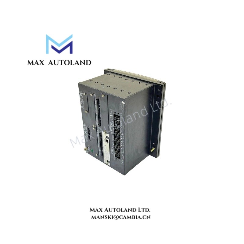
| Physical Interfaces | Front RS232, Rear 10/100Base-T RJ45 Ethernet / Fiber Optic |
Backplane Bus Communication and I/O Scaling
The F650 series utilizes a high-speed backplane bus architecture to manage deterministic data exchange between the base unit and its associated I/O and communication modules. The F-suffix I/O card slot configuration provides discrete digital input and output scaling suitable for breaker trip/close commands, status monitoring, and interposing relay logic. Firmware flash compatibility within the F650 platform ensures that configuration files and logic developed in EnerVista 650 Setup software maintain consistency across hardware revisions without requiring logic recompilation.
Protection Functions (ANSI Device Numbers)
- 50/51 P/N/G: Phase, Neutral, and Ground Instantaneous / Time Overcurrent
- 67 P/N/G: Directional Phase, Neutral, and Ground Overcurrent
- 27 / 59: Phase Undervoltage / Overvoltage
- 81 U/O/R: Underfrequency, Overfrequency, and Rate of Change of Frequency (df/dt)
- 50BF: Breaker Failure protection
- 25: Synchrocheck / Synchronism Verification
- 79: Automatic Reclosing (Multi-shot programmable logic)
Frequently Asked Questions
Q: Does the F650BFBF1G0HIC support hot-swap replacement of the I/O card?
A: No. The I/O card (F-suffix slot) must be configured and installed with the unit de-energized. Settings are stored in the base unit’s non-volatile memory and will be retained upon power restoration.
Q: What is the maximum power consumption of the unit?
A: The typical power consumption is less than or equal to 30 W under normal operating conditions with all communication ports active.
Q: Is the Ethernet communication redundant?
A: Yes. The G-suffix communication card provides redundant Ethernet hardware capabilities, supporting protocols such as IEC 61850 for substation automation networks.
Field Installation Guidelines
- Mounting: Install the unit in a 4U half-rack panel cutout. Ensure the mounting flange seals properly against the panel to maintain the IP54 protection rating.
- Power Wiring: Connect the power supply to the H-suffix high-voltage input terminals. Verify polarity for DC supplies (110 – 250 VDC) and phase alignment for AC supplies (110 – 230 VAC).
- CT/VT Connections: Use shielded twisted pair cables for all current and voltage transformer secondary wiring. Ground the shield at the relay end only to prevent ground loops.
- Communication Cabling: For the G-suffix Ethernet port, use CAT5e or higher rated cables. If fiber optic is utilized, ensure the transceiver matches the G-suffix hardware modification.
- Environmental: The C-suffix (Harsh Environment) conformal coating provides protection against moisture and chemical contaminants. However, avoid installing the unit in locations with direct water spray or submersion unless the IP65 kit is additionally installed.


