Overview
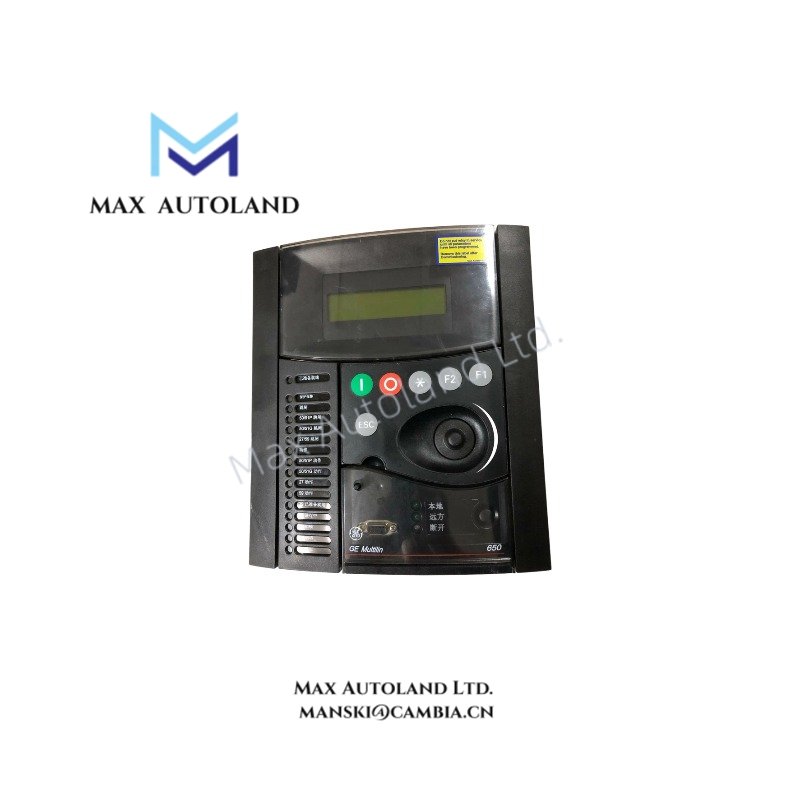
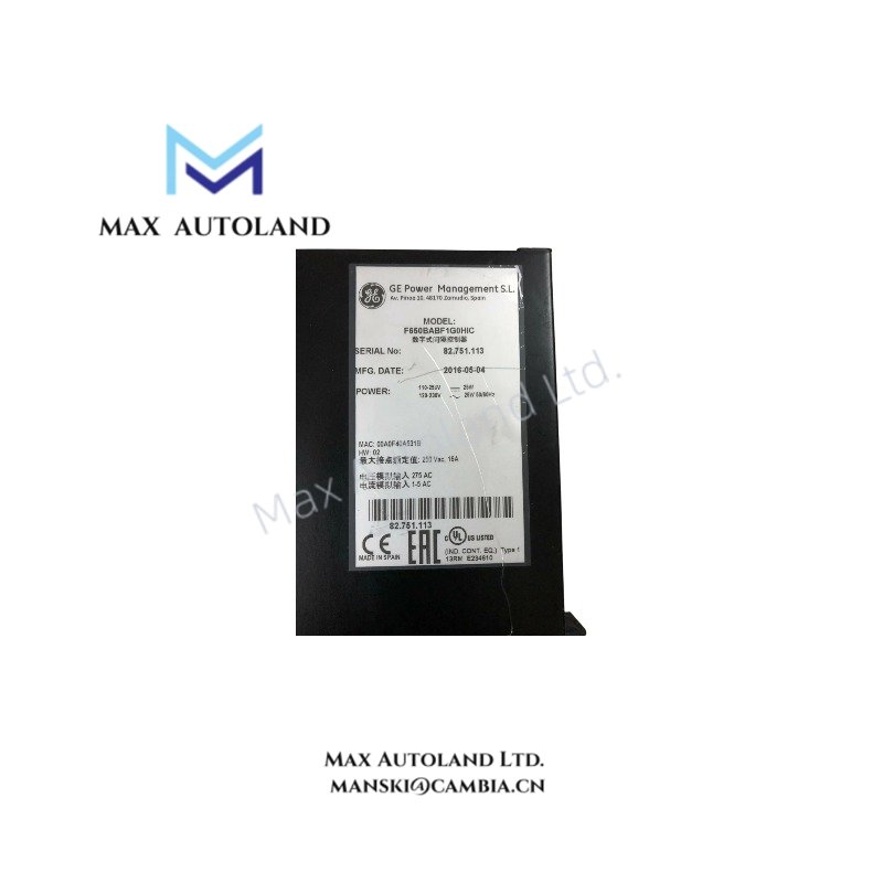
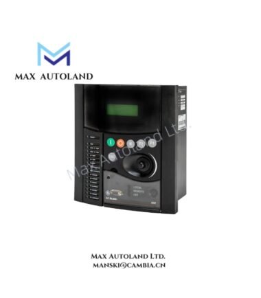
The GE Multilin F650BABF1G0HIC, also cataloged as the F650 Feeder Protection and Control System, operates as a dedicated hardware component for protection, control, and monitoring of feeder circuits within utility and industrial electrical substations.
Suffix Breakdown & Model Matrix
| Code Segment | Configuration Slot | Specification / Meaning |
|---|---|---|
| F650 | Base Model | Multilin F650 Feeder Protection and Control System |
| B | Language & Target | English front panel overlay and default language |
| A | Phase Currents | 1 A / 5 A three-phase current inputs (software selectable) |
| B | Ground Current | 1 A / 5 A ground/earth current input |
| F | Auxiliary Power Supply | High Range: 110-250 V DC / 120-230 V AC |
| 1 | Slot F (I/O Board 1) | Standard I/O Board: 16 Digital Inputs + 8 Outputs |
| G | Slot G (I/O Board 2) | Standard I/O Board: 16 Digital Inputs + 8 Outputs |
| 0 | Slot H (I/O Board 3) | Empty / No board installed in this slot |
| H | Rear Communications | Ethernet (10/100 Base-TX RJ45) + RS485 / RS232 ports |
| I | Protocols | Enhanced Protocols: Includes IEC 61850, DNP 3.0, and Modbus RTU/TCP |
| C | Harsh Environment | Conformal coating on printed circuit boards (for moisture/dust protection) |
Hardware Specifications
| Parameter | Specification |
|---|---|
| Model | F650BABF1G0HIC |
| Brand | GE (General Electric) |
| Series | Multilin F650 |
| Enclosure Case | 4U half-rack standard horizontal chassis, suitable for panel mounting |
| Human-Machine Interface (HMI) | Integrated graphical LCD display, navigation keys, programmable LEDs, and a front RS232/USB port for local laptop configuration |
| Operating Temperature | -20 deg C to +60 deg C (-4 deg F to 140 deg F) |
| Storage Temperature | -40 deg C to +85 deg C (-40 deg F to 185 deg F) |
| Humidity | Up to 95% non-condensing (enhanced by the “C” conformal coating option) |
| Ingress Protection | IP52 (Front panel) |
| Auxiliary Power Supply | 110-250 V DC / 120-230 V AC |
| Phase Current Inputs | 1 A / 5 A three-phase (software selectable) |
| Ground Current Input | 1 A / 5 A |
| Digital Inputs | 32 (16 per I/O board x 2 boards) |
| Digital Outputs | 16 (8 per I/O board x 2 boards) |
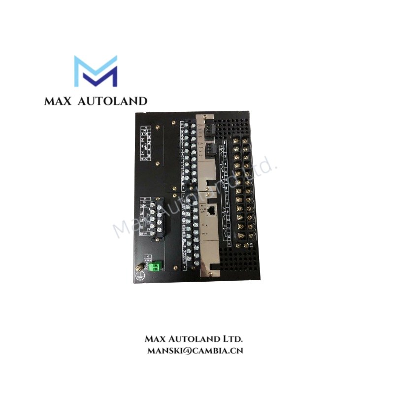
| Rear Communication Ports | Ethernet (10/100 Base-TX RJ45) + RS485 / RS232 |
Backplane Bus Communication and I/O Density Scaling
The F650 architecture utilizes a high-velocity backplane bus for inter-module communication, facilitating deterministic data exchange between the CPU and the I/O boards. The I/O density scaling is achieved through the slot-based architecture (Slots F, G, H), allowing for a maximum configuration of 48 digital inputs and 24 digital outputs. The FlexLogic™ engine executes custom control logic equations directly on the device, eliminating the need for external PLCs for interlocking and automation tasks.
Frequently Asked Questions
Q: Does the F650 support hot-swapping of the I/O boards?
A: No, the I/O boards are not hot-swappable. The device must be de-energized and isolated from the power supply before performing any hardware module replacement.
Q: What is the firmware upgrade compatibility for the F650?
A: Firmware updates are performed via the front RS232/USB port or through the rear Ethernet port using GE’s proprietary software tools. Ensure the firmware version is compatible with the existing hardware revision and that a full configuration backup is performed prior to any update.
Q: How does the device handle communication protocol redundancy?
A: The rear communication ports support both Ethernet and serial connections. IEC 61850, DNP 3.0, and Modbus RTU/TCP protocols can be configured to operate simultaneously, providing protocol-level redundancy for SCADA integration.
Field Installation Guidelines
- Mounting: Install the 4U half-rack chassis into a standard panel cutout. Secure the unit using the provided mounting brackets and screws. Ensure the panel provides adequate support for the weight of the device and connected wiring.
- Wiring: Use shielded twisted-pair cables for all current and voltage input signals to minimize electromagnetic interference. Properly ground the shield at one end (typically the device end) to the designated grounding terminal.
- Grounding: Connect the device’s ground terminal to the substation’s main earth ground bus using a dedicated ground wire. A low-impedance ground path is critical for accurate metering and protection performance.
- Torque: Tighten all terminal block screws to the manufacturer’s specified torque values. Over-tightening can damage the terminals, while under-tightening can lead to resistive heating and connection failure.
- Conformal Coating: The “C” suffix indicates the presence of conformal coating. While this provides enhanced protection against moisture and dust, it is not a substitute for installing the device in a properly sealed enclosure if the environment is excessively harsh.