")
")
")
Overview
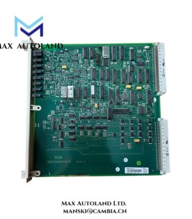
The ABB DSBB110A, also cataloged as the DSBB110A Bus Backplane Module, operates as a dedicated hardware component for inter-module signal distribution and backplane communication within ABB Master System networks. The module provides the physical connection path between installed control modules, enabling power and data transfer through the rack backplane architecture.
Hardware Specifications
| Parameter | Specification |
|---|---|
| Model | DSBB110A |
| Brand | ABB |
| Origin | Sweden |
| Product Type | Bus Backplane Module |
| System Platform | ABB Master System |
| Function | Backplane communication and module interconnection |
| Installation Method | Rack-mounted |
| Backplane Interface | Integrated bus connection architecture |
| Module Compatibility | ABB Master System modules |
| Weight | Not specified in available documentation |
| Dimensions | Not specified in available documentation |
| Operating Temp | Not specified in available documentation |
| Power Consumption | Passive backplane component; consumption not separately specified |
Firmware Flash Compatibility and Backplane Integration
The DSBB110A forms part of the ABB Master hardware infrastructure by providing the electrical pathways required for communication between installed modules. Backplane-based architectures depend on correct connector engagement and bus continuity to maintain deterministic data exchange.
When controllers, communication interfaces, or I/O modules undergo firmware updates, compatibility verification should include the associated rack and backplane assembly. Proper seating and contact integrity are necessary to maintain uninterrupted bus operation throughout the system lifecycle.
Frequently Asked Questions
Q: Does the DSBB110A require firmware configuration?
A: No firmware is typically associated with the backplane module itself. Firmware management is performed within the connected controller, communication, or I/O modules.
Q: Can the DSBB110A be replaced while adjacent modules remain installed?
A: Replacement procedures should follow ABB maintenance instructions. Power isolation is generally recommended before removing hardware that forms part of the system backplane structure.
Q: What should be inspected if communication faults occur after installation?
A: Verify module seating, backplane connector condition, mechanical alignment, grounding continuity, and the integrity of all rack-mounted hardware connections.
Field Installation Guidelines
- Inspect all backplane connectors for bent pins, contamination, or mechanical damage before installation.
- Mount the backplane assembly according to the rack alignment features provided by the host system.
- Ensure all modules are fully inserted and secured to maintain continuous bus contact.
- Maintain separation between communication wiring and high-current power conductors.
- Apply shield grounding according to site electrical standards and ABB system documentation.
- Verify cabinet grounding continuity before energizing the system.
- Perform communication diagnostics after installation to confirm proper backplane operation.
- Record rack position and hardware configuration for maintenance tracking.
ABB Top Products
Customers Also Viewed
Contact: Manski Wong +86 18030205725 manski@cambia.cn


Reviews
There are no reviews yet.