Overview
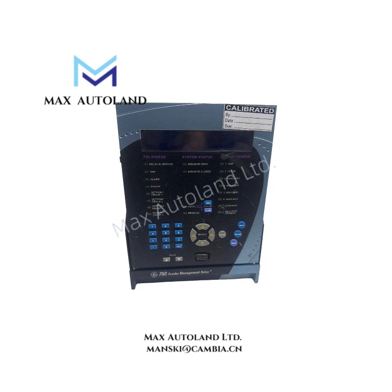
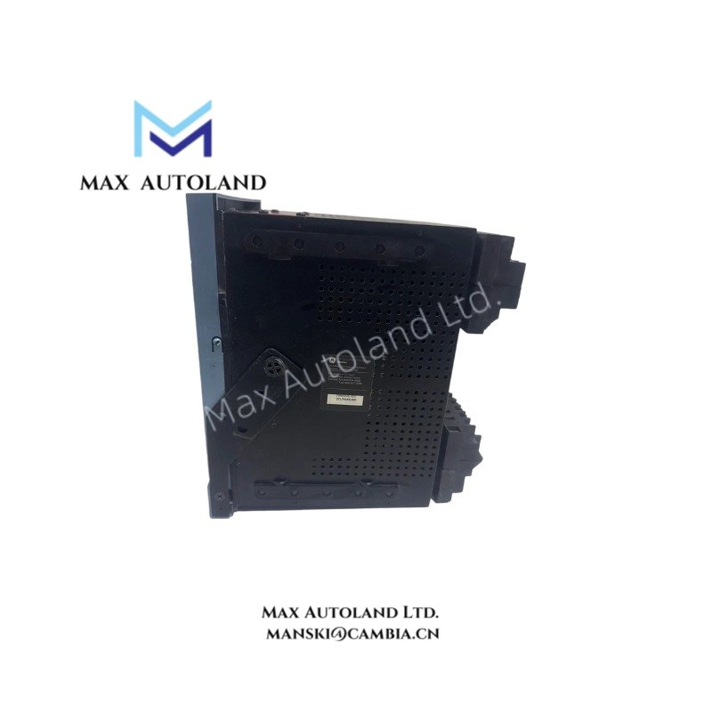
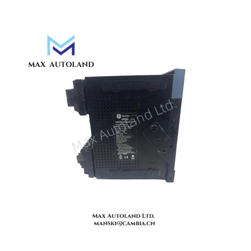
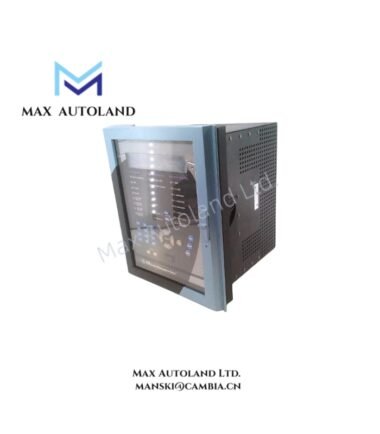
Configured for electrical fault monitoring and breaker control in medium-to-high voltage substation automation systems, the GE Multilin SR 750-P1-G1-S1-HI-A20-R-E (SR750 Feeder Management Relay) provides direct physical/electrical execution. It functions as a microprocessor-based protection device designed to continuously monitor phase, zero-sequence, and sensitive ground currents, executing programmed trip and control logic based on measured electrical parameters.
Hardware Specifications
| Parameter | Specification |
|---|---|
| Model | SR 750-P1-G1-S1-HI-A20-R-E |
| Brand | GE Multilin |
| Origin | Canada |
| Weight | 10 lbs 10.4 oz (4.8 kg) |
| Dimensions | 7.0 in x 9.0 in x 7.0 in (17.8 cm x 22.9 cm x 17.8 cm) |
| Power Supply Input | 88 to 300 VDC; 70 to 265 VAC at 48 to 62 Hz |
| Phase Current Inputs | 1 A secondary secondary rating |
| Zero-Sequence Current Inputs | 1 A secondary rating |
| Sensitive Ground Current Inputs | 1 A secondary rating |
| Analog Outputs | Eight channels, 4-20 mA current loops |
| Local Interface | Enhanced display with red Breaker Closed LED indicator |
| Tariff Code | 85364900 |
Deterministic Network Connectivity and Firmware Verification
The relay integrates within advanced industrial control infrastructures, utilizing deterministic network communication channels to transmit transient records and physical telemetry. Firmware flash compatibility protocols dictate that any logic configuration updates require specific verification algorithms to prevent memory corruption across the local backplane. The architecture supports synchronization across high-density I/O scaling setups, isolating control logic processing from communication bus line disturbances to ensure continuous protective elements stay online during high-velocity data bus transitions.
Frequently Asked Questions
Q: What are the installation restrictions regarding hot-swapping the SR750 chassis?
A: This device does not support hot-swap capabilities. Power must be completely isolated from the main supply terminals and the current transformer (CT) shorting blocks must be fully engaged before removing or inserting the relay unit into its case to prevent lethal high-voltage inductive arcing.
Q: How should the eight 4-20 mA analog outputs be grounded to mitigate signal interference?
A: All 4-20 mA analog loops must utilize individually shielded twisted-pair cabling. The shields must be tied to a clean instrument ground at the panel side only, avoiding multiple ground points to eliminate ground loops that introduce measurement deviation into the downstream PLC or DCS analog input cards.
Field Installation Guidelines
- CT Shorting Block Validation: Ensure all external current transformer circuits are routed through shorting switch blocks. Opening a CT secondary circuit while energized will generate destructive overvoltages, causing immediate physical damage to the terminal block insulation and relay sensing inputs.
- Chassis Grounding: A dedicated, low-impedance copper conductor (minimum 4.0 mm sq) must be secured firmly from the rear chassis ground lug directly to the primary station ground grid. This mitigates electrostatic discharge risks and ensures internal surge suppression components function optimally.
- Terminal Torque Specifications: Tighten all power and current input terminal screws to the manufacturer-specified torque matrix to prevent high-resistance connections under vibration-prone substation environments.