
Overview
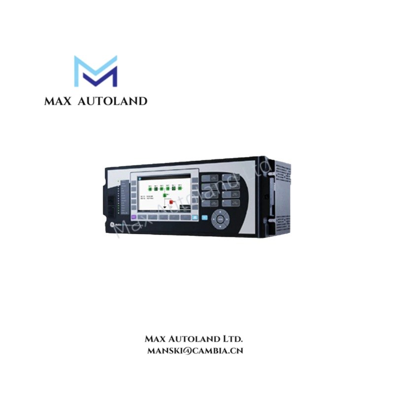
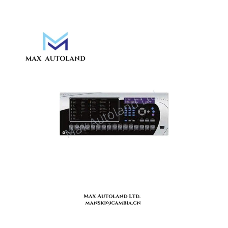
The GE T60N00HUHF8LH6TM8NP6CU6CWXX, also cataloged as the GE T60 Transformer Protection System, operates as a dedicated hardware component for high-speed sub-transmission and transmission transformer protection within Universal Relay (UR) platform architectures. Configured as a smart part number, this assembly interfaces directly with current transformers, voltage transformers, and circuit breaker trip circuits to execute multi-winding transformer differential and overcurrent algorithms.
Hardware Specifications
| Parameter | Specification |
|---|---|
| Model | T60N00HUHF8LH6TM8NP6CU6CWXX |
| Brand | GE (General Electric) |
| Origin | USA |
| Weight | 5.2 kg |
| Dimensions | 177 mm x 483 mm x 240 mm (4U 19-inch rackmount width) |
| Operating Temp | -40 to +70 deg C |
| Power Consumption | 15 W nominal, 30 W maximum |
| Current Inputs | 1 A / 5 A source-programmable |
| Voltage Inputs | 0 to 300 VAC continuous |
| Protection Execution | Phase, ground, restricted earth differential (87R, 87G, 87P) |
Deterministic Industrial Control & Network Firmware Matrix
The modular design leverages a deterministic backplane bus communication velocity architecture to handle synchronous phase-angle calculations across multi-winding zones. To minimize protocol latencies during high-density I/O telemetry streaming, the unit employs dual-redundant EtherNet/IP and Profinet deterministic networks that execute high-speed GOOSE messaging structures down to sub-millisecond timelines. Firmware flash compatibility checks ensure that the physical hardware configuration profile matches the system boot block parameters, preventing mismatched I/O density scaling across legacy UR configurations and mitigating runtime chassis synchronization errors.
Frequently Asked Questions
Q: Does this specific configuration support hot-swap capabilities for the I/O modules?
A: No. Power must be completely isolated from the chassis before servicing or replacing internal modules. Removing any active module under load will interrupt the internal backplane bus communication velocity loops and trigger an immediate system fault or unrecoverable hardware state.
Q: How is the dual-frequency 50/60 Hz compatibility managed during grid fluctuations?
A: The device utilizes an integrated tracking algorithm that dynamically samples the incoming voltage or current waveforms from the designated tracking source. It locks onto the fundamental frequency between 40 Hz and 65 Hz, continuously adjusting its internal digital filters to maintain phase angle accuracy during dynamic system shifts.
Field Installation Guidelines
- Chassis Grounding: A dedicated, low-impedance copper ground wire (minimum 12 AWG / 3.3 mm sq) must be secured directly from the rear chassis grounding stud to the main panel ground bus bar. Ensure all surface contact points are clean, paint-free, and torqued to factory specifications to suppress electromagnetic interference (EMI).
- CT Circuit Secondary Safety: Current transformer (CT) secondary circuits must never be open-circuited while the primary circuit is energized. High-voltage transients capable of breaking down insulation and destroying internal digital logic will occur. Use shorting blocks on all current input modules during diagnostic testing or maintenance intervals.
- Shielded Cable Separation: Route all low-level signal paths and communication cables in dedicated conduits separate from high-voltage AC control circuits or motor power cables. All cable shields must be grounded at one end only (typically the panel entry point) to eliminate induced ground loops.


