Overview
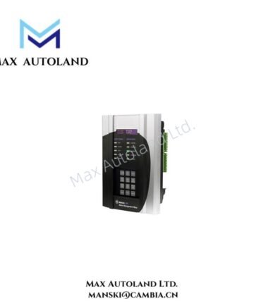
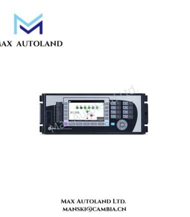
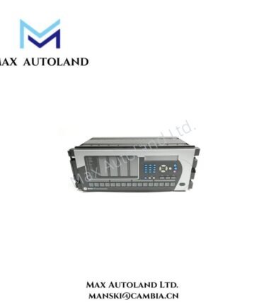
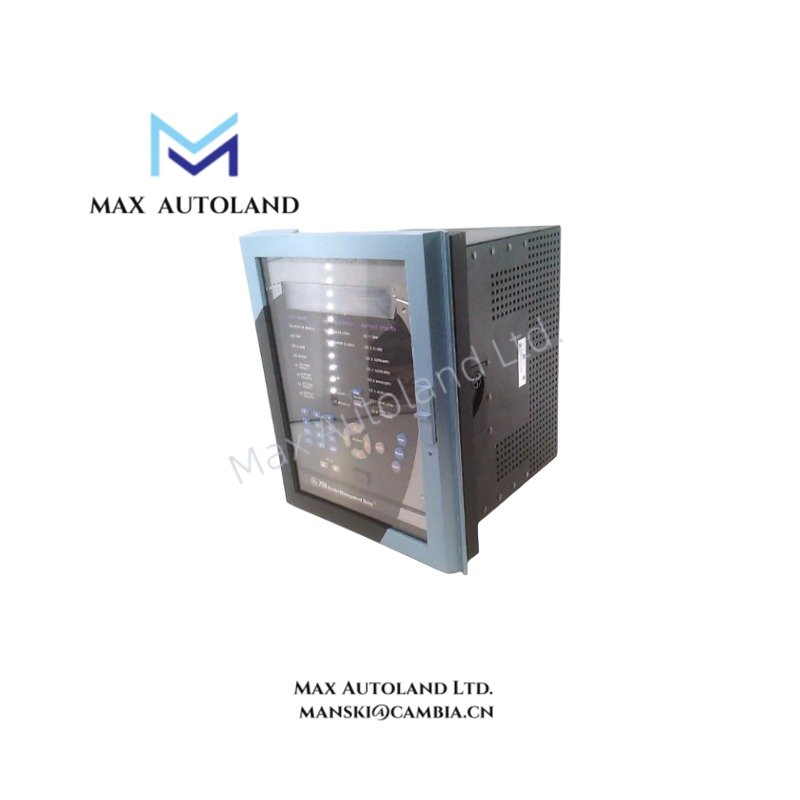
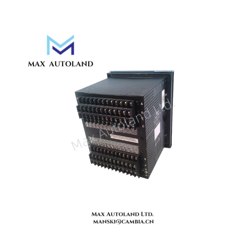
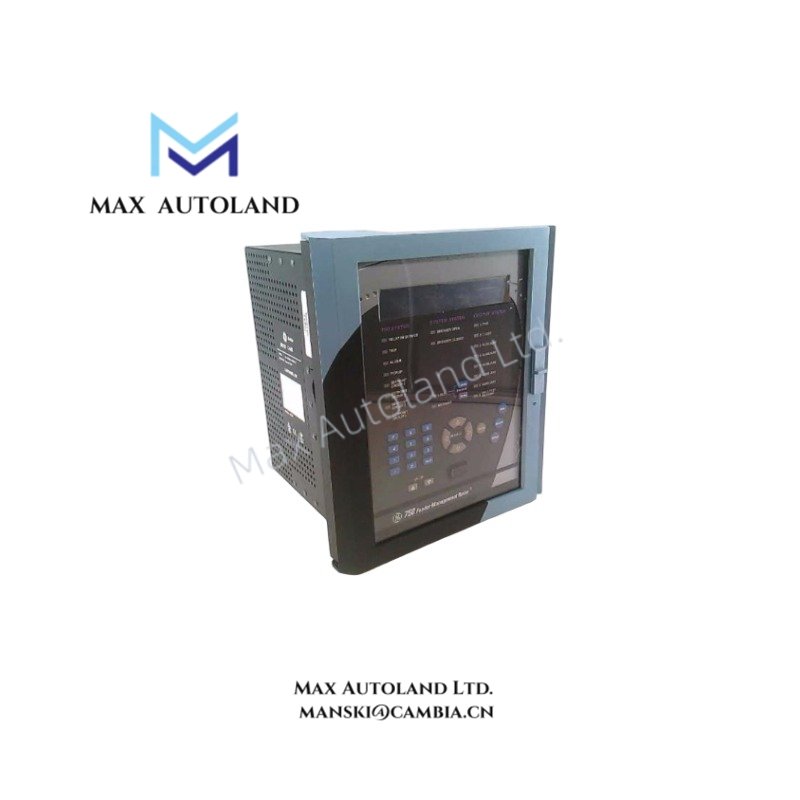
The GE Multilin 750-P5-G5-S5-HI-A20-R-E, also cataloged as the 750 Series Feeder Management Relay, operates as a dedicated hardware component for distribution feeder protection, control, and monitoring within utility and industrial power systems.
Suffix Breakdown & Model Matrix
| Code Segment | Parameter | Description / Specification |
|---|---|---|
| 750 | Base Model | SR750 Feeder Management Relay System |
| P5 | Phase Current Inputs | 5 A Phase Current Transformer (CT) Secondaries |
| G5 | Ground Current Inputs | 5 A Ground/Zero-Sequence CT Secondary |
| S5 | Sensitive Ground Input | 5 A Sensitive Ground CT Secondary (for high-impedance grounded systems) |
| HI | Control Power Range | High-range power supply: 88 – 300 VDC or 70 – 265 VAC @ 48-62 Hz |
| A20 | Analog Outputs | Eight (8) channels of 4 – 20 mA programmable analog outputs |
| R | Display Indicator | Red LED for “Breaker Closed” status indicator |
| E | Display Type | Enhanced Display (Vacuum Fluorescent Display / Advanced LCD screen) |
Hardware Specifications
| Parameter | Specification |
|---|---|
| Model | 750-P5-G5-S5-HI-A20-R-E |
| Brand | GE Multilin (GE Vernova) |
| Category | Controls & Indicators / Overcurrent Relay |
| Weight | 14.00 lbs (6.35 kg) |
| Phase Current Inputs | 5 A nominal |
| Ground Current Inputs | 5 A nominal (Zero Sequence) |
| Sensitive Ground Input | 5 A nominal |
| Control Power Supply | 88 – 300 VDC / 70 – 265 VAC @ 48 – 62 Hz |
| Analog Outputs | 8 channels, 4 – 20 mA programmable |
| Status Indicator | Red LED (Breaker Closed) |
| Display Type | Enhanced Display |
| Communication Protocols | Modbus RTU, DNP 3.0 |
Communication Bus and I/O Scaling
The SR750 series utilizes a backplane bus architecture for high-velocity data exchange between the relay and connected I/O modules. Firmware flash compatibility is maintained across the SR750 family, allowing for standardized configuration via GE’s EnerVista 750 Setup software. The eight 4-20 mA analog outputs are programmable for mapping system parameters such as phase current, voltage, or frequency to external SCADA or control systems.
Frequently Asked Questions
Q: What is the function of the Red LED (R) indicator on this model?
A: The Red LED (R) is a dedicated front-panel status indicator that illuminates when the associated circuit breaker is in the closed position, providing immediate visual confirmation of the breaker’s state.
Q: What are the control power supply requirements for the HI option?
A: The HI (High-range) power supply option supports a wide input range of 88 to 300 VDC or 70 to 265 VAC at 48 to 62 Hz, accommodating diverse substation power sources.
Q: How many analog output channels are available and what is their signal type?
A: This model (A20) provides eight (8) channels of 4-20 mA programmable analog outputs for transmitting real-time system data.
Field Installation Guidelines
- Mounting: Install the relay in a standard 19-inch rack mounting cutout using the drawout-unit chassis mechanism. Ensure the chassis is securely fastened to prevent vibration-induced loosening.
- Wiring: Use shielded twisted-pair cables for current transformer (CT) inputs to minimize electromagnetic interference. Properly ground the shield at one end (typically the relay end) to ensure signal integrity.
- Grounding: Connect the relay’s grounding terminal to a dedicated substation ground bus. Verify that the ground connection is secure and meets local electrical codes.
- Torque Specifications: Tighten all terminal screws to the manufacturer’s recommended torque values to prevent overheating and ensure reliable electrical contact.
- Environmental: Although this unit does not feature the harsh environment (H) conformal coating option, it should still be installed in a clean, dry environment within the specified operating temperature and humidity ranges.