Overview
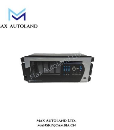
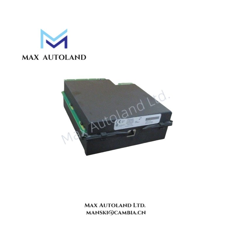
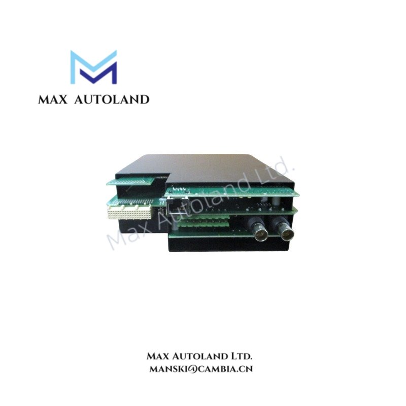
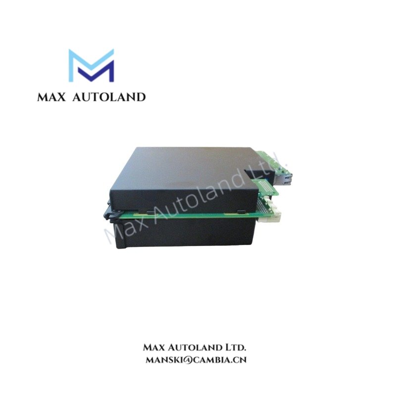
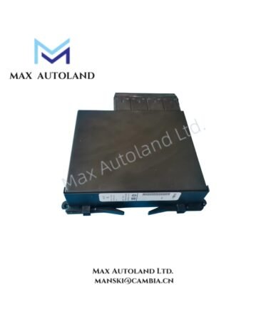
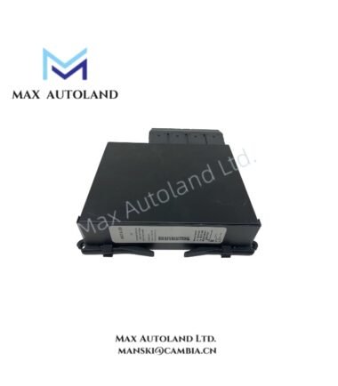
Configured for high-speed protection data exchange and IEC 61850 peer-to-peer communications in the GE Multilin Universal Relay chassis, the GE UR9NV (UR-9NV CPU/Comm Module) provides direct backplane bus execution and dual-Ethernet protocol handling.
Hardware Specifications
| Parameter | Specification |
|---|---|
| Model Brand | GE Multilin (GE Vernova) |
| Origin | Ontario, Canada / USA |
| Weight | Approx. 0.35 kg |
| Dimensions | Standard UR Series Single Slot Module |
| Operating Temp | -40 degC to +60 degC |
| Power Consumption | < 8 W via Backplane (5 VDC) |
| Ethernet Ports | 2 x 10/100/1000 Mbps Copper or Fiber (LC/ST optional) |
| Supported Protocols | IEC 61850 Ed.2 (GOOSE/SV), DNP3, Modbus RTU/TCP, IEC 60870-5-104 |
| Time Sync | IEEE 1588 PTP, IRIG-B, SNTP |
| Cyber Security | AAA (RADIUS/TACACS+), RBAC, Syslog |
Backplane Bus Communication Velocity and Firmware Flash Compatibility
The UR9NV communicates with I/O and low-level modules across the internal UR backplane at deterministic scan rates. Firmware version 9.x must be loaded to match the relay family (G60, T60, N60, etc.) configuration file. Down-rev flashing to version 8.x is not supported on 9-series hardware. The module supports hot-swap insertion provided the chassis power supply has adequate margin for the additional ~300 mA backplane draw.
Frequently Asked Questions
Q: Can a UR9NV be installed in an older UR relay originally shipped with a UR8CPU?
A: Yes, provided the EnerVista project is migrated to firmware v9.x and the I/O module firmware is also compatible. Physical slot fit is identical.
Q: Does the UR9NV require external time sync hardware for IEC 61850 sampled values?
A: Sub-microsecond synchronization requires either an IRIG-B source or IEEE 1588 Grandmaster. SNTP alone is insufficient for SV applications.
Q: Are both Ethernet ports independently configurable?
A: Yes. Port A and Port B can be assigned separate IP subnets for redundant network segmentation (PRP/HSR supported).
Field Installation Guidelines
- ESD Handling: Wear a grounded wrist strap before removing the module from its anti-static packaging.
- Slot Placement: Install into the CPU designated slot (typically leftmost in the UR chassis). Do not mix CPU and I/O slots.
- Ethernet Cabling: Use CAT5e or better STP cabling for noise immunity in substation environments. Terminate shield to chassis ground at one end only.
- Torque: Secure front panel mounting screws to 0.8 Nm. Verify all RJ45 or fiber connectors are fully seated before closing the door.