Overview
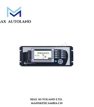
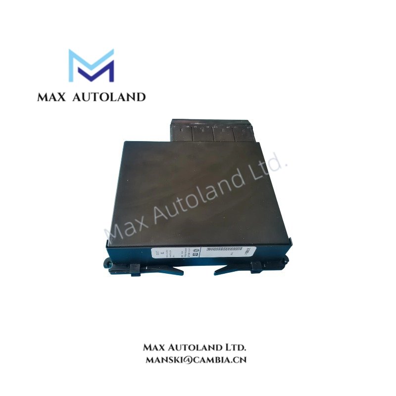
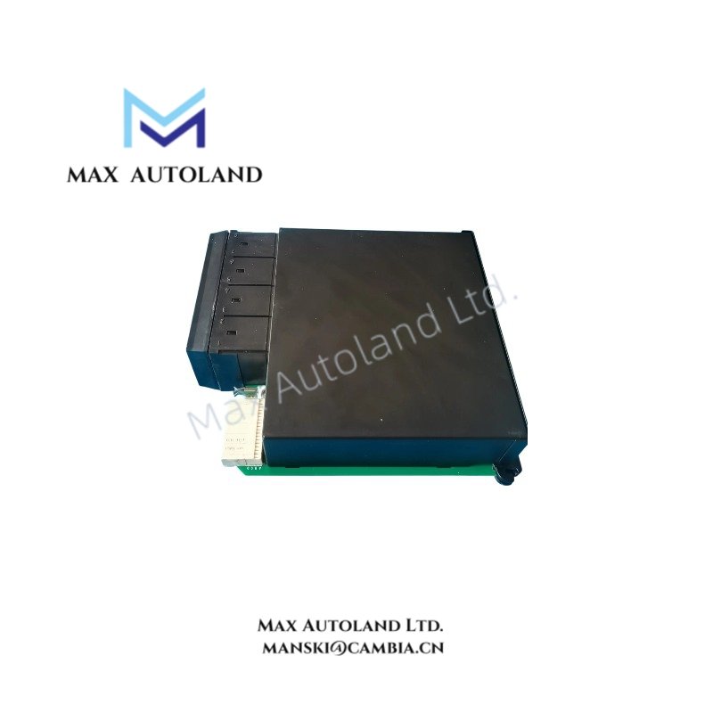
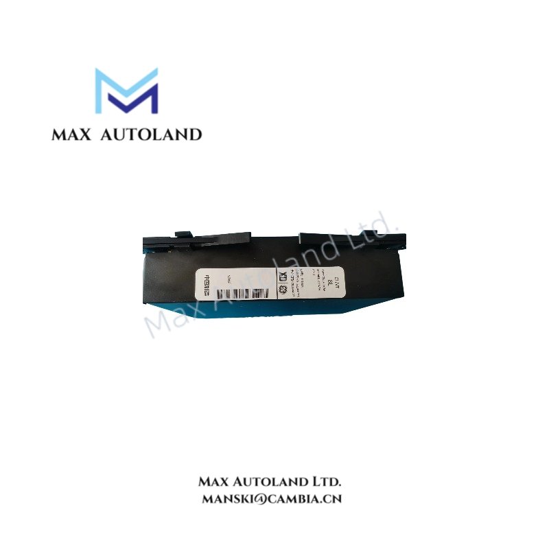
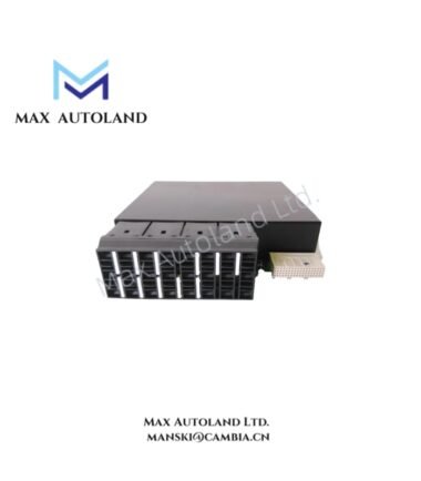
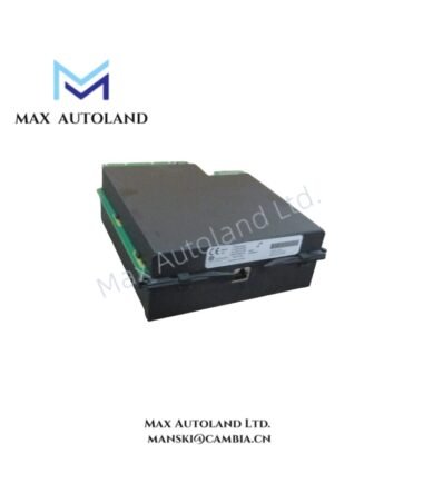
The GE UR8LM, also cataloged as the UR-8LM 8-Channel Transducer Input Module, operates as a dedicated hardware component for low-level signal acquisition within the GE Multilin Universal Relay system. It processes milliamp and low-voltage signals from field transmitters, converting them via internal A/D conversion for protection and metering logic execution.
Hardware Specifications
| Parameter | Specification |
|---|---|
| Model Brand | GE Multilin |
| Origin | Ontario, Canada |
| Weight | Approx. 0.25 kg |
| Dimensions | Standard UR Series Single Slot Module |
| Operating Temp | -40 degC to +85 degC |
| Power Consumption | < 5 W (via Backplane) |
| Number of Channels | 8 Independent Channels |
| Input Range | 0 to 20 mA, 4 to 20 mA, -1 to +1 mA |
| Input Impedance | 249 Ohm |
| Isolation | Channel-to-Channel, Channel-to-Ground |
| Accuracy | +/- 0.1% of Full Scale or +/- 20 uA |
| A/D Conversion | 16-bit Resolution |
Firmware Flash Compatibility and Backplane Bus Execution
The UR8LM interfaces with the Universal Relay main processor via the internal backplane bus. Firmware revisions must match the host relay’s UR version to ensure data integrity during high-speed sampling cycles. The module supports deterministic data exchange without affecting the relay’s primary protection timing. Hot-swapping is supported only when the UR chassis power budget allows for additional module current draw without exceeding the total supply rating.
Frequently Asked Questions
Q: Does the UR8LM require calibration upon installation?
A: No. The module utilizes factory-set scaling. Calibration is performed via software mapping within the EnerVista UR Setup tool by correlating the raw 16-bit integer value to the engineering units of the connected transducer.
Q: What is the maximum backplane current consumption?
A: The module draws approximately 200 mA from the 5 VDC backplane supply. Verify the remaining power budget of the UR relay chassis before installation.
Q: Can this module be used for high-voltage analog inputs?
A: No. This is a low-level input module. Applying voltages above the specified range will damage the input circuitry. Use external shunts or voltage dividers for high-energy signals.
Field Installation Guidelines
- ESD Precautions: Always wear a grounded wrist strap when handling the module. Do not touch the connector pins or electronic components.
- Slot Identification: Install the module into the designated I/O slot (F, G, or H) as defined in the specific UR relay ordering code. Incorrect slot placement will result in the relay failing to recognize the hardware.
- Wiring Practice: Use shielded twisted pair cabling for all analog inputs. Connect the shield drain wire to the chassis ground at the relay end only to prevent ground loops.
- Torque Spec: Tighten terminal block screws to 0.5 Nm (4.4 lb-in). Ensure no bare wire strands are exposed outside the terminal housing.